Eureka AIR delivers breakthrough ideas for toughest innovation challenges, trusted by R&D personnel around the world.

Handle Assembly Providing Unlimited Roll

Pending Publication Date: 2021-02-11
FLEXDEX INC
View PDF0 Cites 2 Cited by
  • Summary
  • Abstract
  • Description
  • Claims
  • Application Information

AI Technical Summary

Benefits of technology

The patent text describes a handle assembly for a tool that allows for improved control and flexibility when using the tool. The handle assembly has an unlimited-roll handle assembly and an arm attachment, which can be connected to the user's arm through a joint. The joint provides degrees of freedom between the appearance of the tool and the user's arm, allowing for smoother and more precise use of the tool. The handle assembly is controlled through an end-effector actuation transmission member, such as a cable or wire, which allows for independent control of the tool's jaws. Overall, the handle assembly provides better control and flexibility for the user while using the tool.

Problems solved by technology

While the handle may fit or conform in the user's hand, palm, and / or fingers in the nominal condition (i.e., prior to any roll rotation), it may no longer continue to fit / conform with the user's hand during and after the roll rotation.
In fact, during such rotation, the handle may start to collide with areas of the hand that are holding the device, typically limiting the amount of roll rotation and / or requiring repositioning of the handle within the surgeon's hand to achieve maximum roll rotation at the end-effector.
Thus, many of these devices may require more than one hand to operate or may require repositioning of the device during operation within a user's hand in order to continue to roll in a single direction beyond a limited amount of roll.
In addition, a device that is repositioned to continue roll rotation is usually not ergonomic and more difficult to operate due to loss of access to the input joint / mechanism between the tool frame / tool shaft.
Attempts have been made to address the challenge of limited rotation and reduced ergonomics by providing a rotational joint in the handle assembly between the stationary portion of the handle that is held generally by a user's hand and palm (and possibly by finger(s) and / or thumb) in the nominal condition and the roll portion (e.g. a dial, handle dial, rotation dial or the like) that is rotated with respect to the stationary portion about its center axis generally by the user's finger(s) and / or thumb; these attempts have met this challenge with only limited success, in part because rolling the device in this manner may result in winding of internal transmission members when rolling the roll portion (e.g., dial, handle dial, rotation dial or the like) relative to the stationary portion.
Furthermore, laparoscopic devices are becoming more complex and catering to challenging laparoscopic procedures.
Engagement of a handle input (e.g., handle input lever) to actuate the opening / closing of an end-effector having a jaw at the end of the tool shaft typically results in high loads generated between the stationary portion of the handle assembly held by the user and the rotatable portion of the handle assembly (e.g., dial) that interface with each other to allow rotation.
The result of the high load between these independent bodies is typically an increase in frictional resistance to roll rotation which limits the surgeon's ability to use fine rotation input at the handle assembly to precisely control the end-effector roll rotation.
Due to the complexity in simultaneously transmitting and providing roll, articulation, and actuation functionality to the end-effector in such devices, as well as the limitation of working within a tight volume to incorporate features to meet these functionalities, it is challenging to incorporate assemblies, mechanisms, joints, and bodies that meet the structural and interface requirements to be able to provide the aforementioned functionalities.

Method used


Image

  • Handle Assembly Providing Unlimited Roll
  • Handle Assembly Providing Unlimited Roll
  • Handle Assembly Providing Unlimited Roll

Examples


Embodiment Construction

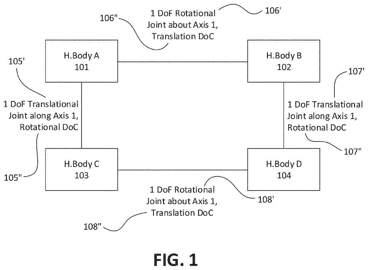
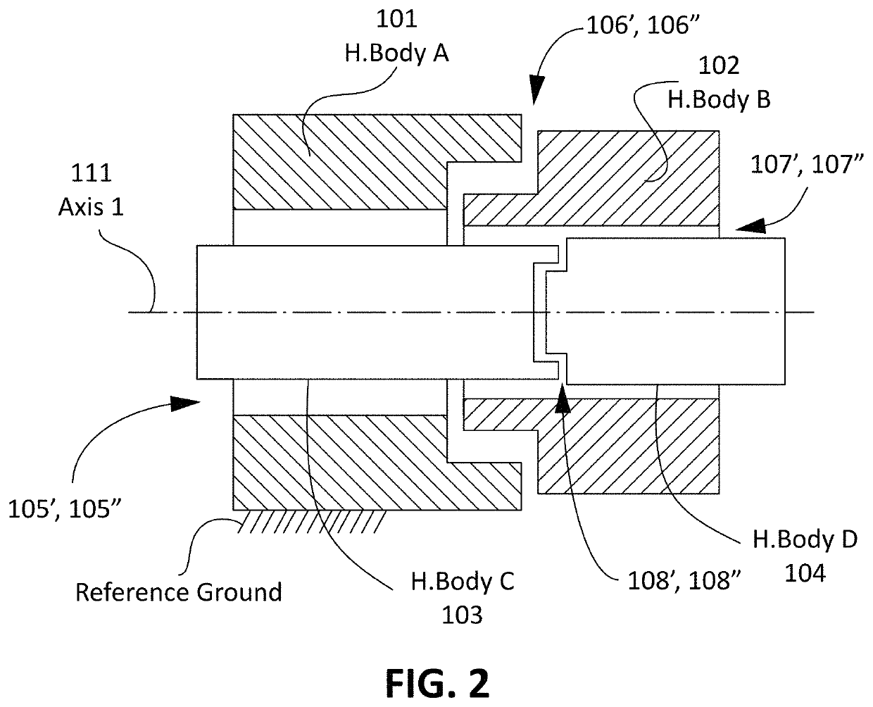
[0100]Described herein are apparatuses including an unlimited-roll handle assembly. Although the unlimited-roll handle assemblies described herein may be incorporated into any apparatus (e.g., device, tool, system, machine, etc.), described herein in particular are apparatuses including unlimited-roll handles assemblies at a proximal region of an elongate tool frame (e.g., a tool shaft or including a tool shaft) having an end-effector at the distal end of the tool frame. The apparatus may include a forearm attachment at the proximal end; the forearm attachment may allow one or more degrees of freedom between the user's forearm and the tool frame while the user's hand grips the unlimited-roll handle assembly. The apparatus may be articulating; for example, the tool frame may include an input joint between the unlimited-roll handle assembly and the tool frame that may capture movement (e.g., pitch and yaw movements) between the handle assembly and the tool frame for transmission to an...


PUM


Abstract

An example roll handle assembly includes a handle body, a roll body, a closure body, and a shuttle body. The roll body is coupled to the handle body and has a rotational degree of freedom about a roll axis relative to the handle body. The roll body is translationally constrained along the roll axis relative to the handle body. The closure body is coupled to the handle body and has one or more degrees of freedom of motion relative to the handle body. The shuttle body is coupled to the roll body and the closure body, and has a translational degree of freedom along the roll axis relative to the roll body. The shuttle body is rotationally constrained about the roll axis relative to the roll body, and has a rotational degree of freedom about the roll axis relative to the closure body.

Description

CROSS REFERENCE TO RELATED APPLICATIONS[0001]This application is a continuation-in-part of U.S. patent application Ser. No. 15 / 943,689, entitled “HANDLE MECHANISM PROVIDING UNLIMITED ROLL”, and filed on Apr. 2, 2018, the contents of which are hereby incorporated herein in their entirety by reference. U.S. patent application Ser. No. 15 / 943,689 is a continuation of U.S. patent application Ser. No. 15 / 284,345, entitled “HANDLE MECHANISM PROVIDING UNLIMITED ROLL”, filed on Oct. 3, 2016, and now U.S. Pat. No. 9,814,451, the contents of which are hereby incorporated herein in their entirety by reference. U.S. Pat. No. 9,814,451 claims priority to U.S. provisional patent application No. 62 / 236,835, filed on Oct. 2, 2015, the contents of which are hereby incorporated herein in their entirety by reference.[0002]This application may also be related to U.S. patent application Ser. No. 15 / 130,915, titled “ATTACHMENT APPARATUS FOR REMOTE ACCESS TOOLS” filed on Apr. 15, 2016, which claimed prior...

Claims


Application Information

Patent Timeline
IPC IPC(8): A61M25/01A61B17/00
CPCA61M25/0136A61B17/00234A61B1/0052A61B2017/00323A61B2017/00424A61B17/062A61B17/2909A61B2017/00017A61B2017/003A61B2017/00442A61B2017/291A61B2017/2929A61B2090/067A61B2090/064A61B1/00066A61B1/00147A61B2017/00438A61B2017/00398A61B2017/00314
Inventor SHARMA, DEEPAKBOWLES, GREGORY BRIANLICHT, JAMES MICHAELZIMMERMAN, ZACHARYAWTAR, SHORYAGEIGER, JAMES DUNCAN
Owner FLEXDEX INC
Why Eureka
Eureka Blog
Learn More