Surveying instrument for and surveying method of surveying reference points

a technology of reference points and surveying instruments, which is applied in the field of surveying instruments and surveying methods of reference points, can solve problems such as interference with the functioning of the system, noisy measurement, and the possibility of detecting false positives, and achieve the effect of simple calibration procedures

Pending Publication Date: 2021-02-11
FNV IP BV
View PDF0 Cites 7 Cited by
  • Summary
  • Abstract
  • Description
  • Claims
  • Application Information

AI Technical Summary

Benefits of technology

[0052]relatively simple calibration procedure.

Problems solved by technology

Higher levels of ambient light could interfere with the functioning of the system.
The use of a moving camera imposes limitations on the signal processing resulting in noisy measurements and the possibility of detecting “ghost” beacons (false positives).
Moreover, this document has no way of identifying the attitude (pitch / roll) of the LED beacons.
Moreover, this document describes a simple time delay method to identify different beacons but that does not allow telemetry of other information.
However, the document does not describe a system to calculate ray angles to the beacons and is thus by nature less accurate.
Regular refractive camera objective lenses can only compromise between chromatic and geometric aberration corrections.
Therefore, a refractive camera objective lens will always show a certain amount of distortion.
Furthermore, tiny imperfection within the lenses, or their surfaces, will introduce further unknown distortions.
Further, such distortions might be dependent on the f-stop used under certain lighting conditions.
While in principle all contributing effects can be measured for an individual objective lens, the effort and uncertainty introduced with every additional corrective measure renders the system known from JP2004325072 and JP2004325073 undesirable.
Not discussed in said documents, temperature and pressure changes to which the camera objective lenses are exposed introduce further distortions to the image.
Thereby rendering data obtained from those known system essentially unreliable.

Method used


Image

  • Surveying instrument for and surveying method of surveying reference points
  • Surveying instrument for and surveying method of surveying reference points
  • Surveying instrument for and surveying method of surveying reference points

Examples


Embodiment Construction

[0073]In general, the present invention relates to surveying objects or tracking of movement of objects by tracking one or more light sources (“beacons”) attached to the object. More specifically, the present invention is directed to cameras used in such surveying or tracking.

[0074]The beacons are, preferably, discerned from other light sources by using correlation techniques. For this means it is important the beacon has a predetermined light pattern. This will be explained in detail below.

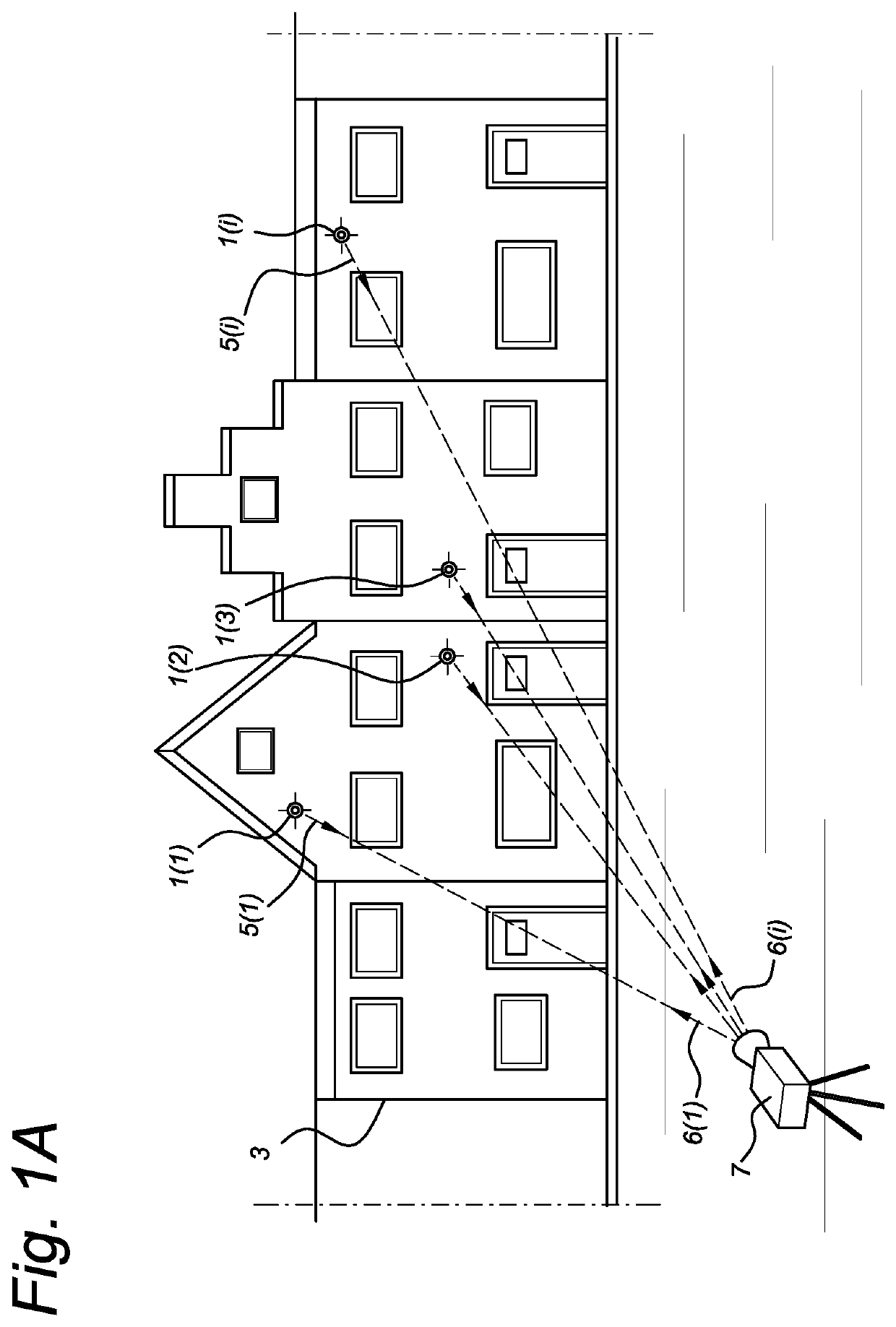
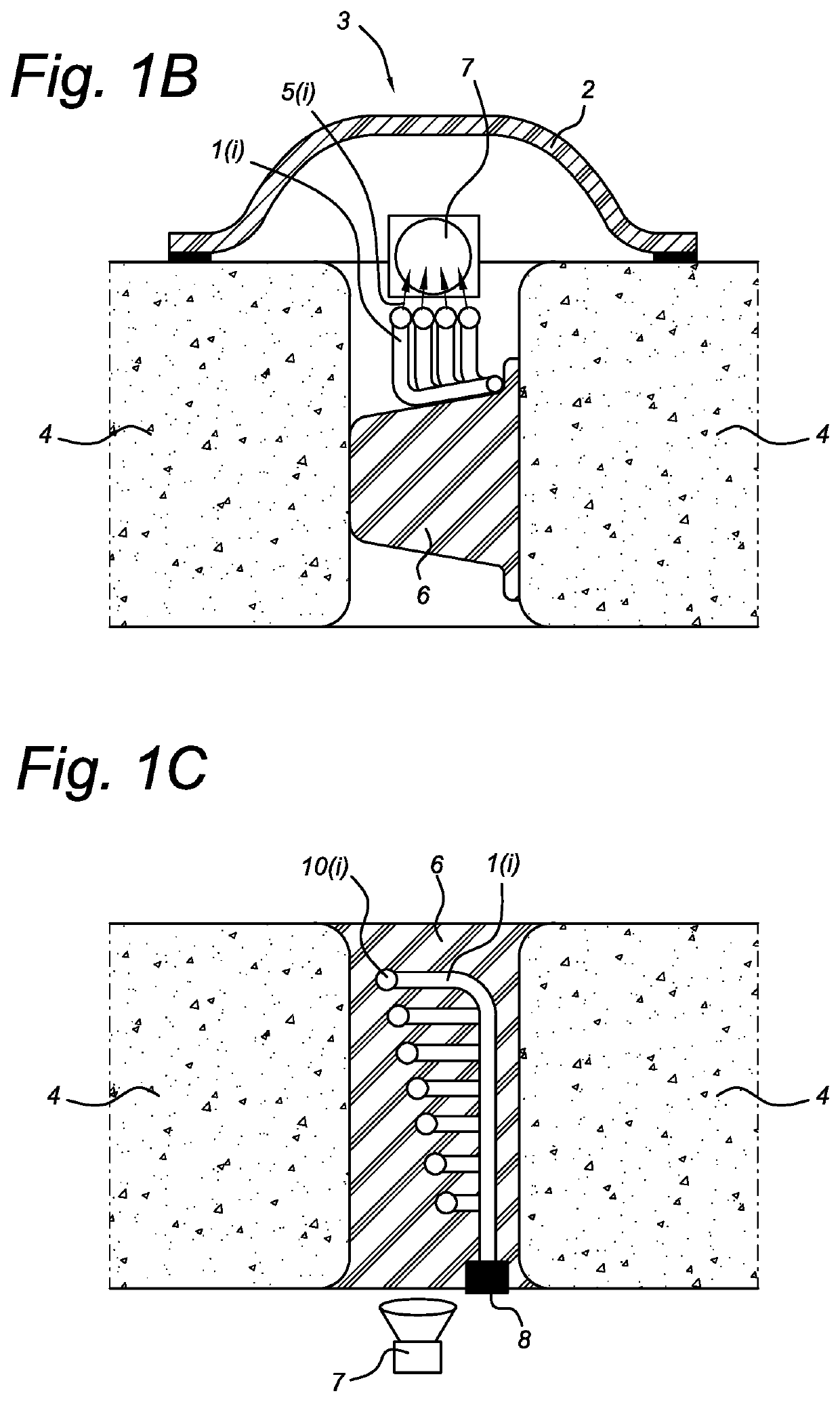
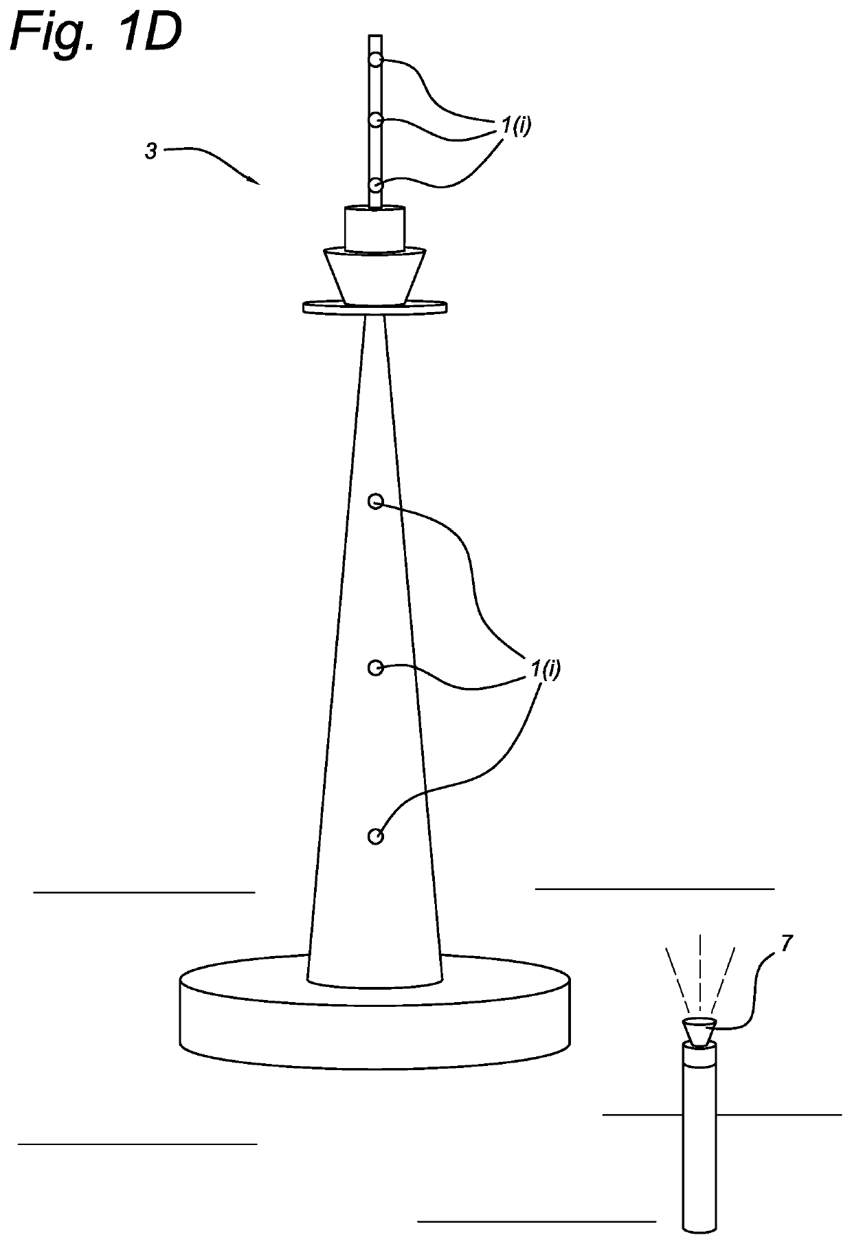
[0075]FIG. 1A shows a possible setup of a system in which an object 3 is monitored. The system comprises a sensor apparatus, like a camera 7. The system also comprises one or more beacons 1(i), i=1, 2, 3, . . . , I, which are attached to object 3. The object 3 is shown as comprising one or more buildings to which the beacons 1(i) are fixed. However, the object 3 may alternatively be any other construction like a tunnel (FIGS. 1B, 1C and 1E), a tower (FIG. 1D), a bridge (FIG. 1F), but also a vehic...


PUM


Abstract

A camera monitors positions on an external object having a beacon (1(i), i=1, 2, . . . , I; 130; 430) attached to it. The apparatus has at least one image sensor (120; 321, 322; 420; 520), an imaging optical element (101) for projecting light on the image sensor (120), and a processing unit (9). The imaging optical element (101) may be non-refractive and receives a light beam (5(i); 131) transmitted from the beacon (1(i); 130; 430) and transfers the light beam (5(i); 131) to the image sensor (120; 321, 322; 420; 520).
The image sensor (120; 321, 322; 420; 520) forms image data based on the received light beam (5(i); 131) and background light. The processing unit (9) processes the image data such that it filters image data components relating to the background light and renders image data components relating to the light beam.

Description

FIELD OF THE INVENTION[0001]The present invention relates to a method of and apparatus for monitoring positions on an object. The present invention may also relate to a surveying instrument for surveying reference marker points and, optionally, relative angles between light beams received from them. Smart beacons are provided as such marker points.BACKGROUND ART[0002]One prior art system is described in patent document WO 2016 / 068715 A1 disclosing an underwater positioning system providing positioning information for a rover, moveable within a reference frame. Such a system may comprise at least one beacon having a light source located at a fixed position within the reference frame, an underwater imaging device mounted to a rover in order to observe the beacon's light source from different viewpoints for the determining of direction data representing a direction or change thereof of the beacon's light source with respect to the rover's imaging device. This known system is required t...

Claims


Application Information

Patent Timeline
Patent Type & Authority Applications(United States)
IPC IPC(8): G01B11/00G01B11/16G01C11/06H04N5/225G06T7/246
CPCG01B11/002G01B11/161G06T7/248H04N5/2256H04N5/2252G01C11/06G01C15/04G01B11/16G01S5/16G01C3/14H04N23/51H04N23/56
Inventor VAN WEEREN, DENNISJONGSMA, AMOUD MARCSEIBERT, JOACHIM ULRICHDE BIJL, MARIO JOSEPHUS
Owner FNV IP BV
Why Eureka
Try Eureka