

Method for reforming amorphous carbon polymer film
a technology amorphous carbon, which is applied in the field of reforming can solve the problems of deterioration of the properties of amorphous carbon polymer films, high thermal shrinkage of conventional amorphous carbon polymers, and increasing the difficulty of void-free filling of high aspect ratio spaces (e.g., ar3), so as to achieve significant improvement of the thermal stability of amorphous carbon films
- Summary
- Abstract
- Description
- Claims
- Application Information
AI Technical Summary
Benefits of technology
Problems solved by technology
Method used
Image

Examples
example 1
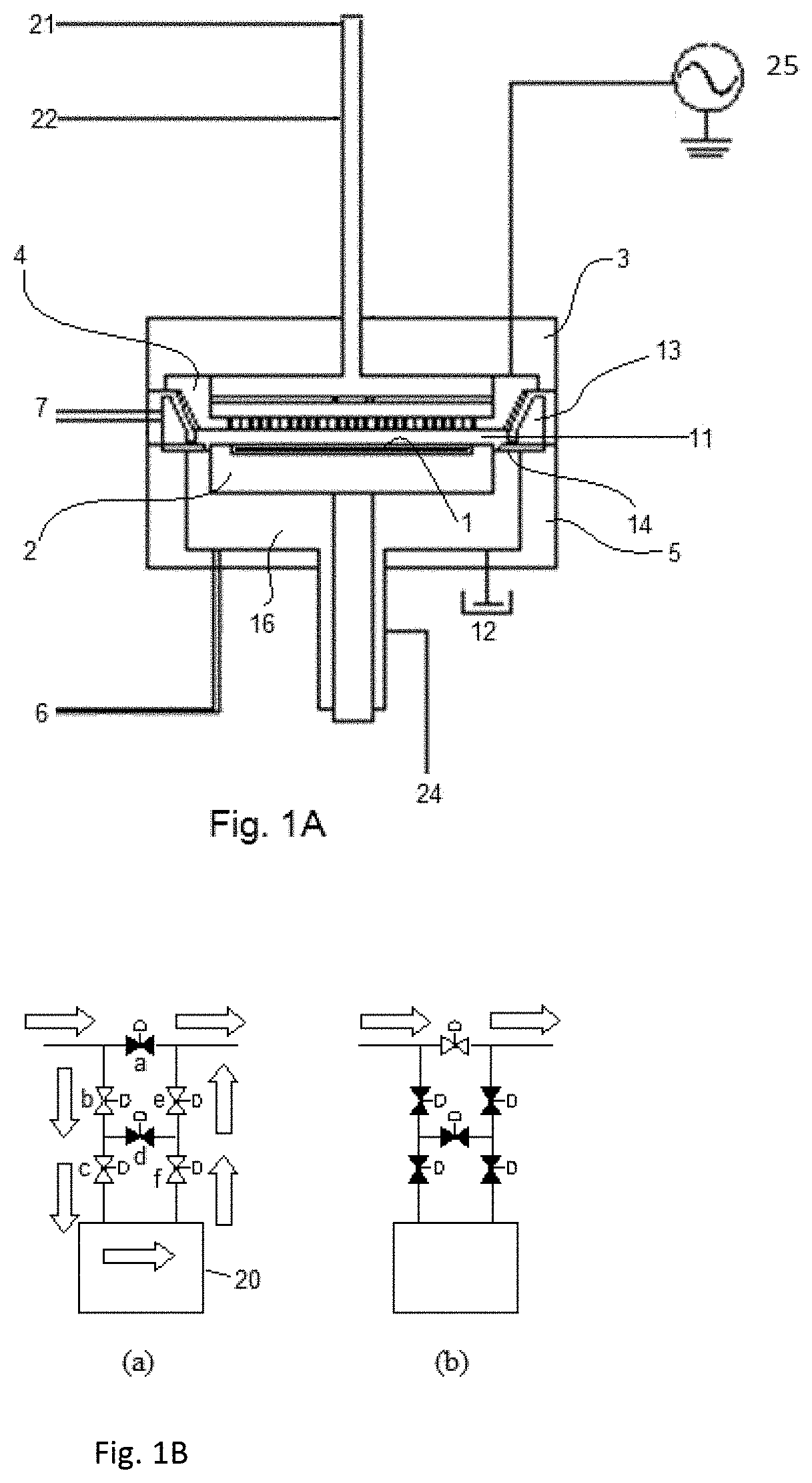
[0054]An amorphous carbon polymer film was deposited on a Si substrate (having a diameter of 300 mm and a thickness of 0.7 mm) by PEALD-like process which is defined in U.S. patent application Ser. No. 16 / 026,711, each deposition cycle of which was conducted as the deposition process illustrated in FIG. 5 under the conditions shown in Table 1 below using the apparatus illustrated in FIG. 1A and a gas supply system (FPS) illustrated in FIG. 1B. As the reformation process as illustrated in FIG. 5 was conducted after every 12 cycles of the PEALD-like process (q=12), under the conditions shown in Table 2 below, which was conducted in the same reaction chamber as in the deposition process. The above combined cycles were repeated 24 times (p=24). The total (final) thickness of the film was roughly 100 nm.
TABLE 1Temp. settingSUS temp (° C.).68SHD temp (° C.)75Wall temp (° C.)75BLT temp (° C.)RTDepoPressure (Pa)1100Gap (mm)14Feed time (s)0.4Purge (s)0.1RF time (s)1.5Purge (s)0.1RF power (W)...
example 2
[0058]Amorphous carbon polymer films (“STD”, “Ar”, and “He”) were formed in the same manner as in Example 1, and properties of the resultant amorphous carbon polymer films were evaluated. The results are shown in Table 4 below.
TABLE 4STD-filmAr-filmHe-filmRI 1.541.531.63Water Contact Angle [°] (25° C.)66.178.960.6Stress [MPa]~0 −120−440RBS [%]C51.051.054.0H46.047.039.0O 3.02.07.0NNDNDNDThermal 50° C. / 30 min0 ——shrinkage [%]125° C. / 30 min10-20——200° C. / 30 min17.67.10.6300° C. / 30 min35.45.40(numbers are approximate)
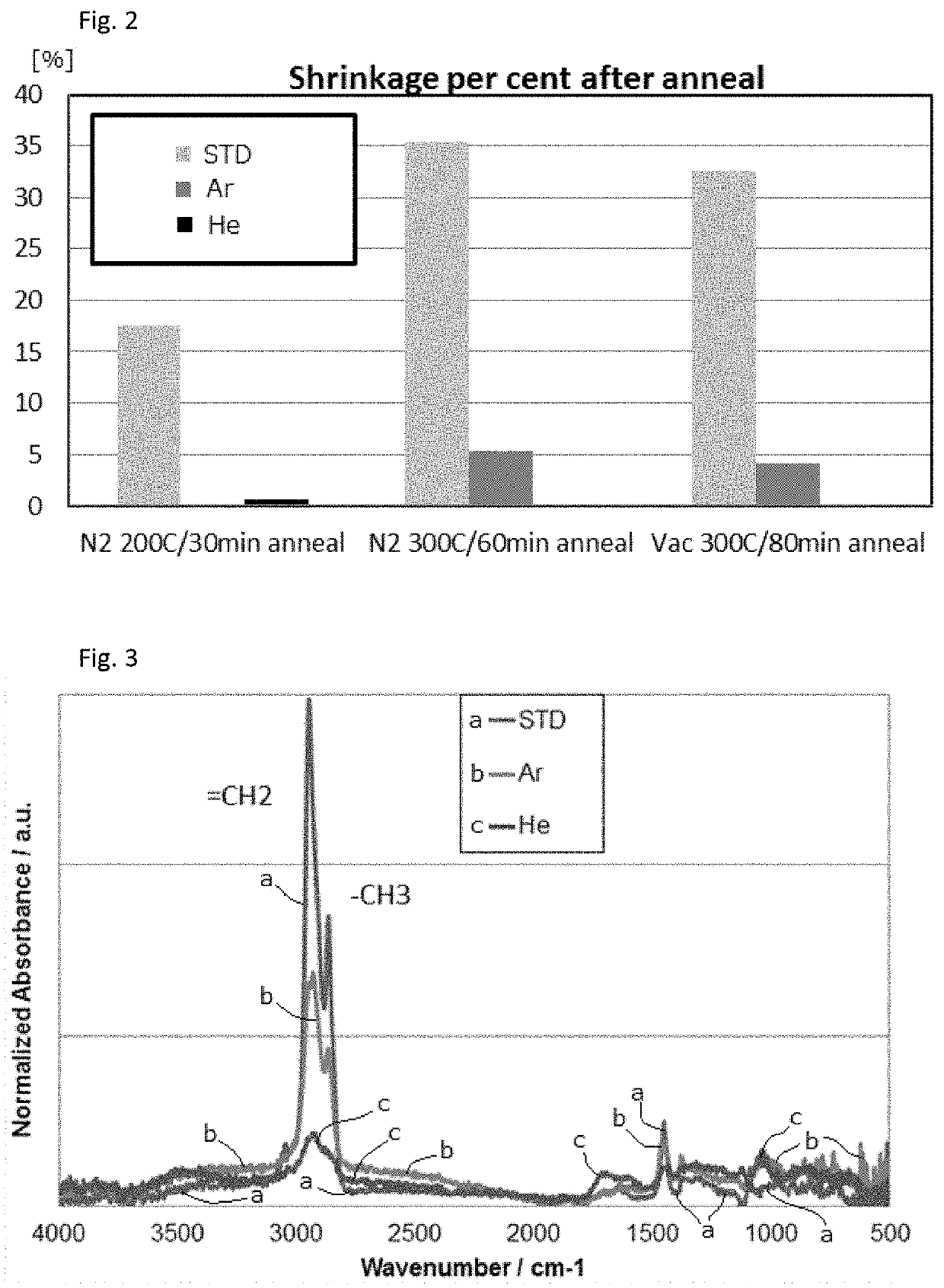
[0059]As shown in Table 4, the thermal shrinkage of the amorphous carbon polymer film with the He plasma treatment (“He-film”) was remarkably lower than that of the amorphous carbon polymer film without plasma treatment (“STD-film”), wherein the thermal shrinkage of the He-film was substantially zero, indicating that the thermal stability of the He-film was excellent. In addition to the results shown in the FTIR of FIG. 3, considering the data in Table 4 showing that the H...
example 3
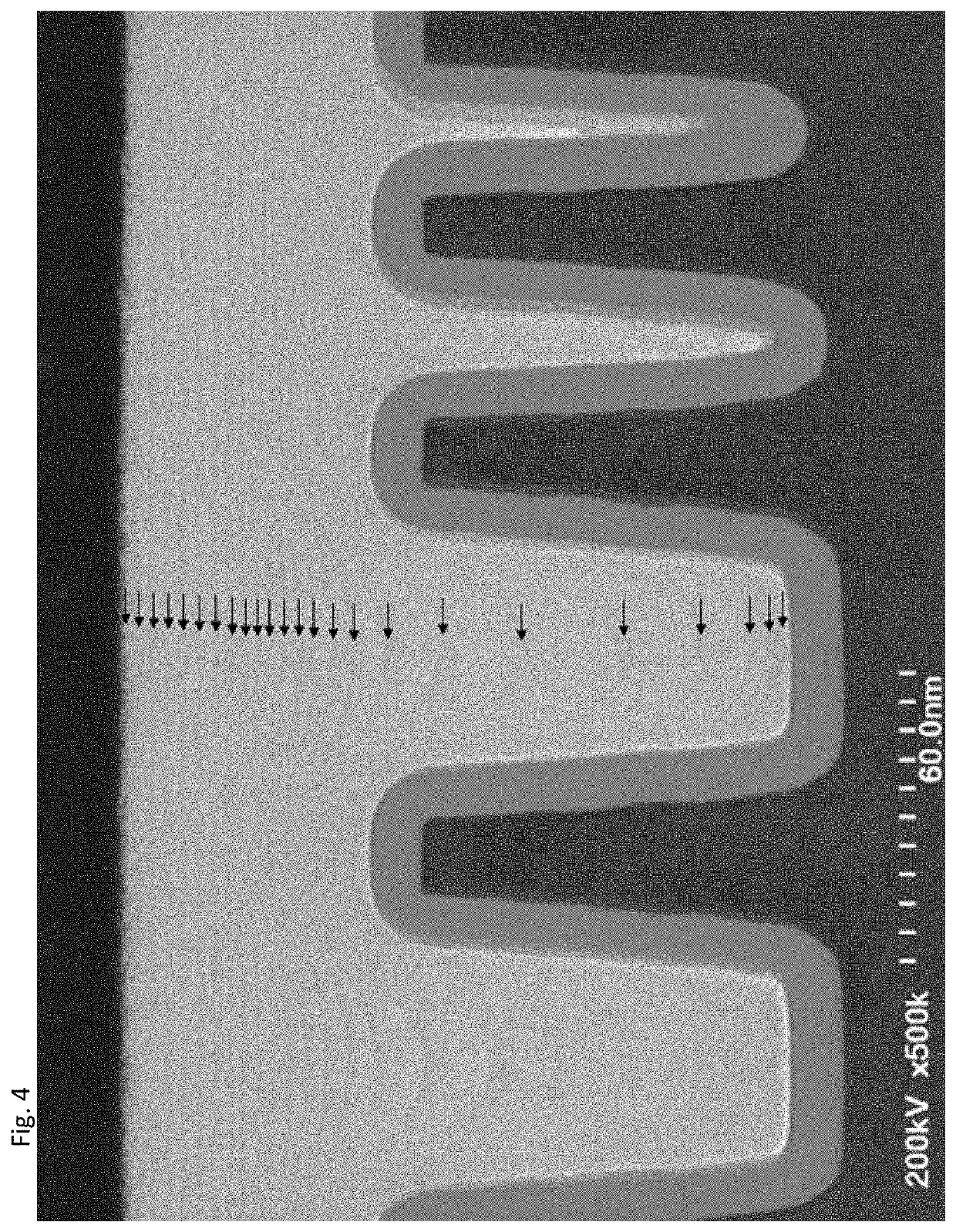
[0061]An amorphous carbon polymer film was deposited on a Si substrate (having a diameter of 300 mm and a thickness of 0.7 mm) with a SiO liner having narrow / deep trenches with an opening of approximately 50 nm, which had a depth of approximately 90 nm (an aspect ratio was approximately 1.8), and narrow / shallow trenches with an opening of approximately 5 to 10 nm, which had a depth of approximately 90 nm, in the same manner as in the reformation with He in Example 1 except that the He plasma treatment was conducted after approximately every 10 nm (24 cycles of deposition) as measured on a planar surface (as blanket deposition).
[0062]FIG. 4 shows a STEM photograph of a cross-sectional view of the trenches subjected to the gap-fill process (bottom-up deposition) with the He plasma treatment, wherein arrows show slightly darker interfaces indicative of the He plasma treatment. Although the darker interfaces are indicative of the He plasma treatment, they do not represent layers reforme...
PUM
| Property | Measurement | Unit |
|---|---|---|
| Thickness | aaaaa | aaaaa |
| Time | aaaaa | aaaaa |
| Time | aaaaa | aaaaa |
Abstract
Description
Claims
Application Information