
Radiation shielded enclosure for spent nuclear fuel cask

Active Publication Date: 2021-02-25
HOLTEC INT
View PDF3 Cites 2 Cited by
  • Summary
  • Abstract
  • Description
  • Claims
  • Application Information

AI Technical Summary

Benefits of technology

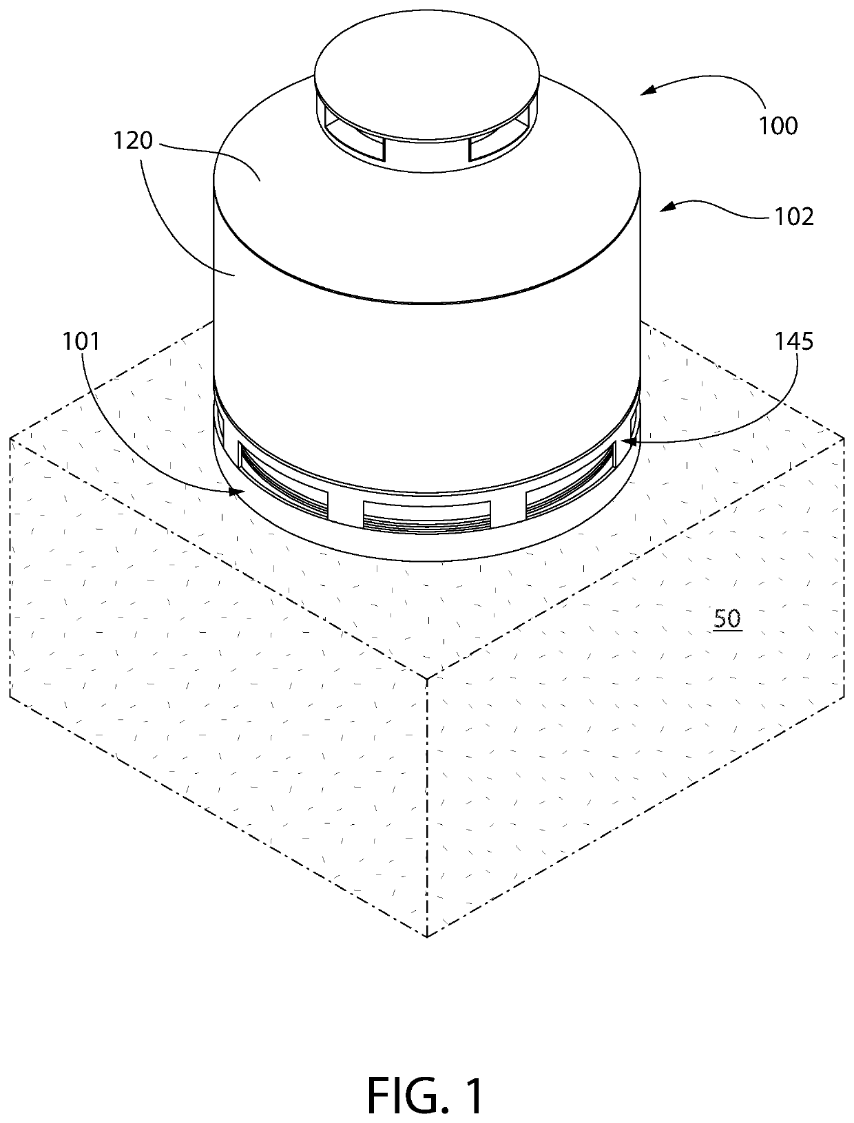
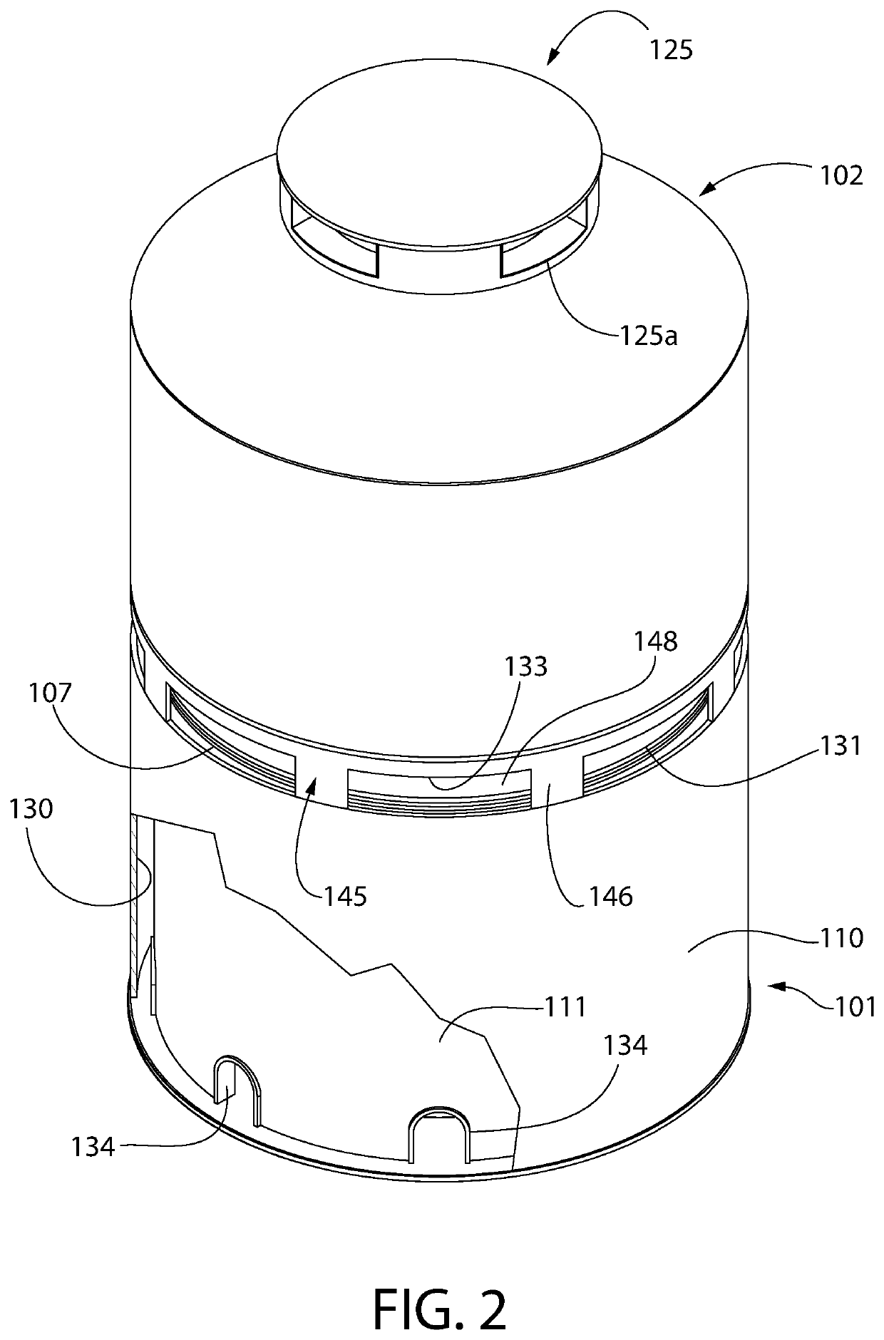
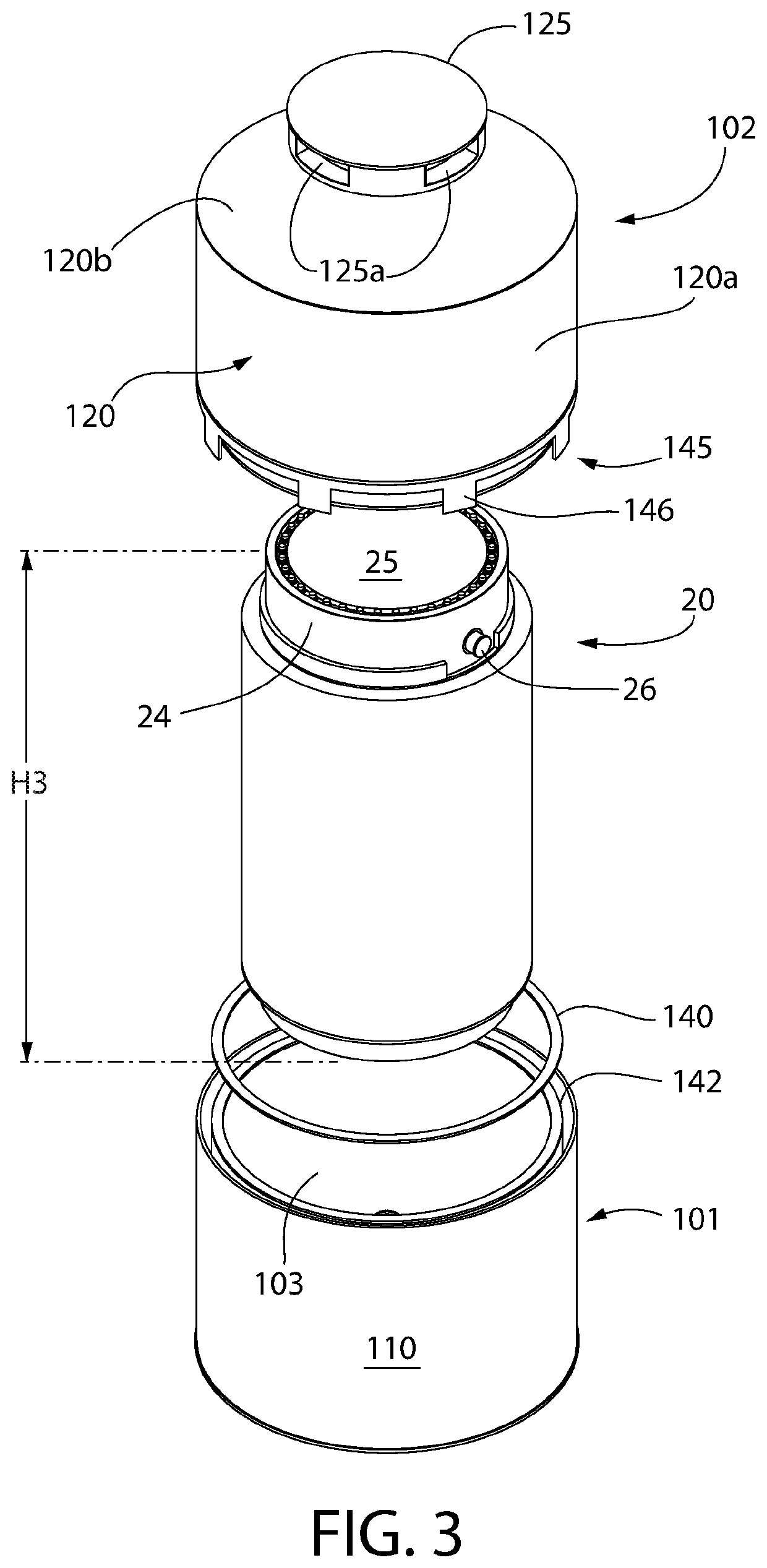
The patent text describes a radiation-blocking shield that is placed over a cask to reduce the amount of radiation that is emitted from the cask. The shield is made of a special material that can block both gamma and neutron radiation. The cask is also ventilated to allow cooling air to flow in and cool the cask naturally. This ventilation system does not require a power source and can be located at remote sites. Overall, this design reduces the radiation levels in the environment where the cask is located, providing a safer workplace for the plant staff. The amount of shielding and the type of shielding used can be varied to achieve significant reduction in radiation dose.

Problems solved by technology

A significant number of dry storage casks containing SNF congregated at an ISFSI pad, however, often accrue radiation dose at the nuclear plant's site boundary that exceeds the allowable limit for the local jurisdiction and / or the federal government.

Method used


Image

  • Radiation shielded enclosure for spent nuclear fuel cask
  • Radiation shielded enclosure for spent nuclear fuel cask
  • Radiation shielded enclosure for spent nuclear fuel cask

Examples


Embodiment Construction

[0035]The features and benefits of the invention are illustrated and described herein by reference to exemplary embodiments. This description of exemplary embodiments is intended to be read in connection with the accompanying drawings, which are to be considered part of the entire written description. Accordingly, the disclosure expressly should not be limited to such exemplary embodiments illustrating some possible non-limiting combination of features that may exist alone or in other combinations of features.

[0036]In the description of embodiments disclosed herein, any reference to direction or orientation is merely intended for convenience of description and is not intended in any way to limit the scope of the present invention. Relative terms such as “lower,”“upper,”“horizontal,”“vertical,”, “above,”“below,”“up,”“down,”“top” and “bottom” as well as derivatives thereof (e.g., “horizontally,”“downwardly,”“upwardly,” etc.) should be construed to refer to the orientation as then desc...


PUM


Abstract

A containment enclosure for shielding an outer cask containing an inner canister loaded with nuclear waste such as spent fuel rods. The enclosure includes a lower base portion at least partially embedded in a concrete pad and an upper radiation shielding portion defined by a shield jacket coupled to and supported by the lower base portion at a circumferential joint. Cavities of the base and shielding portions collectively define a contiguous containment space for the cask. A portion of the cask resides in each of the base and shielding portions which completely enclose and shield the cask to minimize radiation dosage of personnel in the environment surrounding the cask. The cask is cooled by a natural convectively-driven ambient cooling air ventilation system including air inlets at the circumferential joint of the enclosure. The concrete pad may be part of a spent nuclear fuel storage installation comprising plural cask containment enclosures.

Description

CROSS-REFERENCE TO RELATED APPLICATIONS[0001]This application claims the benefit of U.S. Provisional Application No. 62 / 890,813 filed Aug. 23, 2019, which is incorporated herein by reference in its entirety.BACKGROUND[0002]The present invention relates generally to systems for storing used or spent nuclear fuel, and more particularly to an improved nuclear fuel cask which forms part of the storage system.[0003]In the operation of nuclear reactors, the nuclear energy source is in the form of hollow zircaloy tubes filled with enriched uranium, collectively arranged in multiple assemblages referred to as fuel assemblies. When the energy in the fuel assembly has been depleted to a certain predetermined level, the used or “spent” nuclear fuel (SNF) assemblies are removed from the nuclear reactor. The standard structure used to package used or spent fuel assemblies discharged from light water reactors for off-site shipment or on-site dry storage is known as the fuel basket. The fuel baske...

Claims


Application Information

Patent Timeline
IPC IPC(8): G21F5/008G21F5/10G21F5/12
CPCG21F5/008G21F5/12G21F5/10G21F5/02G21F5/08Y02E30/30G21F9/34G21F1/125
Inventor SINGH, KRISHNA P.
Owner HOLTEC INT
Learn More