Pre and Post Anesthetic Cooling Device and Method

a technology cooling device, which is applied in the field can solve the problems of tooth pain, difficult to maintain the target temperature for numbing, watery mess, etc., and achieve the effect of preventing the effect of anesthetic cooling device from losing its efficacy and lowering the temperature of anesthetic cooling devi

Pending Publication Date: 2021-03-11
PILBY GOMEZ JENNIFER
View PDF6 Cites 0 Cited by
  • Summary
  • Abstract
  • Description
  • Claims
  • Application Information

AI Technical Summary

Benefits of technology

[0020]The present device improves patient comfort by providing fast, effective, anesthesia. The cooling device is much faster than topical anesthetics by anesthetizing the tissues in 20-30 seconds versus 2-5 minutes. This time difference is important to practitioners in a busy practice and they would prefer to have fast, effective pain control, especially for use on phobic patients.
[0055]In other embodiments, the present invention uses a solid cooling device without inlets or outlets. In such an embodiment of the anesthetic cooling device, the wand is made from solid conductive metal that has no inlet or outlets connected to an external unit to remove heat. In such an embodiment, the cooling device is cradled inside a cooling cradle at a specific temperature, for example, below 0° C. Heat is transferred from the solid metal inside the cooling device into the cooling cradle through conduction, cooling the metal inside the anesthetic cooling device to the desired temperature. The cooled metal is used to remove heat from the tissues by cooling and therefore numbing the tissues. In such an embodiment, the want may comprise an insulative material such as plastic or other polymer to surround the top or handle portion of the solid cooling wand for hand comfort and to help prevent the anesthetic cooling device from losing efficacy by being warmed by the ambient air.

Problems solved by technology

Ice is effective but drawbacks include a watery mess, and in the mouth causes tooth pain if cold water touches the tooth.
Additional obstacles of using ice are the additional steps of taking it out of the freezer, and preparation to make sure its sanitary for patient use.
A frozen cotton tip applicator melts too fast in the mouth making it difficult to maintain the target temperature for numbing.

Method used


Image

  • Pre and Post Anesthetic Cooling Device and Method
  • Pre and Post Anesthetic Cooling Device and Method
  • Pre and Post Anesthetic Cooling Device and Method

Examples


Embodiment Construction

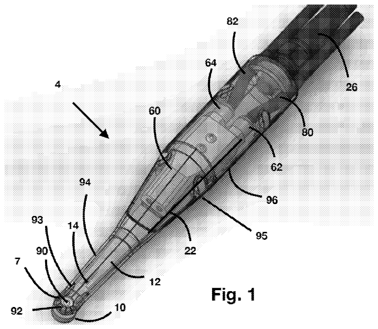
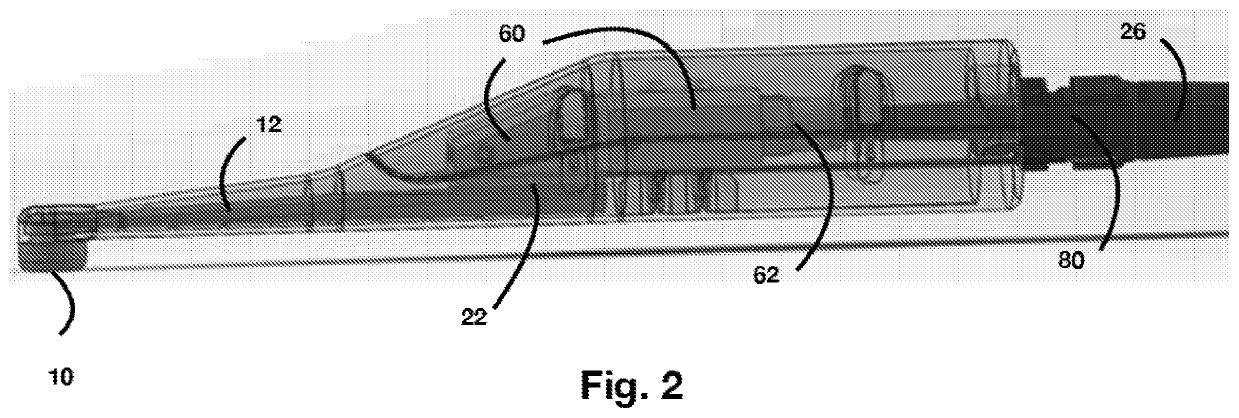
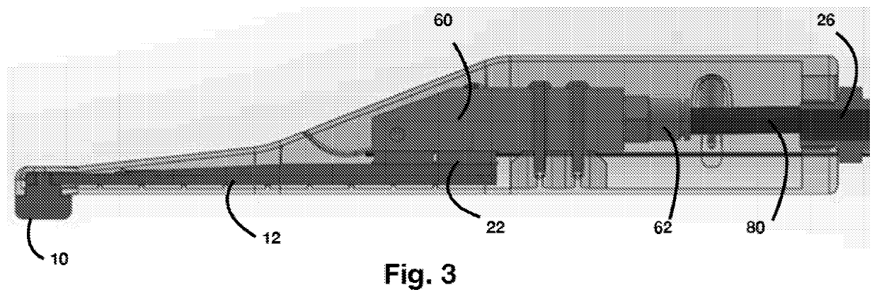
[0075]Further features and advantages of the disclosure, as well as the structure and operation of various embodiments of the disclosure, are described in detail below with reference to the accompanying FIGS. 1-14. Although the disclosure is described in the context of an intra-oral thermoelectric cooling device, the present disclosure includes devices, systems, and methods for use on any tissue.

[0076]In an embodiment of the present invention, a specialized loop coolant block is used. The anesthetic cooling device of the present invention provides transient nerve cooling block of the peripheral nervous system. The anesthetic cooling device of the present invention allows for temperature control cooling of the skin / epidermis or mucous membrane / mucosa, to alleviate pain associated with medical treatment such as injections, curettage, pulp vitality, and skin ablation applied to the human body.

[0077]The anesthetic cooling device of the present invention provides a novel and efficient he...


PUM


Abstract

The present disclosure comprises a pre and post anesthetic cooling apparatus, system, and method for using thereof. In an embodiment, an anesthetic cooling device comprises a wand comprising a proximal end and a distal end opposite the proximal end, a thermoelectric module disposed within the wand having a cold side and a hot side, a TEM heat exchanger disposed within wand and connected to the hot side of the thermoelectric module, wherein a coolant circulates into the TEM heat exchanger through a wand inlet and out of the TEM heat exchanger through a wand outlet, a tip located at the distal end of the wand and connected to the TEM heat exchanger through a thermal conductor; wherein thermal energy is transferred from the tip to the coolant via the thermal conductor and the TEM heat exchanger.

Description

CROSS-REFERENCE TO RELATED APPLICATIONS[0001]The present application claims priority to U.S. Provisional Patent Application No. 62 / 900,149 filed on Sep. 13, 2019 and entitled, “Pre and Post Anesthetic Cooling Device and Method,” and U.S. patent application Ser. No. 16 / 242,823 filed on Jan. 1, 2019 and entitled, “Recirculating Anesthetic Cooling Apparatus and Method,” the entire disclosures of which is incorporated by reference.BACKGROUND OF THE INVENTION1. Field of Invention[0002]The present disclosure relates to an anesthetic cooling device and, more specifically, a device or device accessory to deliver anesthesia through cooling of biological tissue, such as the epidermis, mucocutaneous membranes, teeth, and the oral mucosa, thereby anesthetizing tissue by inhibiting nerve conduction through cooling providing a pain free injection.2. Description of Related Art[0003]There is a constant search for ways to avoid the invasive, and often painful, nature of the injection, and to find mo...

Claims


Application Information

Patent Timeline
Patent Type & Authority Applications(United States)
IPC IPC(8): A61M19/00A61F7/00
CPCA61M19/00A61F7/0085A61F2007/0096A61F2007/0076A61F2007/0087A61F2007/0056A61F2007/0075A61F2007/0054A61F7/007A61F2007/0285A61M2205/3606A61M2205/3673A61M2205/3368A61M2205/362A61M2205/366A61M2209/086
Inventor PILBY GOMEZ, JENNIFERMORRISON, JOSHUA
Owner PILBY GOMEZ JENNIFER
Why Eureka
Try Eureka