Electrical connecting element
a technology of connecting elements and connecting wires, applied in the direction of insulated conductors, cables, knitting, etc., can solve the problems of labor-intensive connection by sewing and insufficient reliability, and achieve the effect of excellent reliability and easy connection to stretch wires
- Summary
- Abstract
- Description
- Claims
- Application Information
AI Technical Summary
Benefits of technology
Problems solved by technology
Method used
Image
Examples
first embodiment
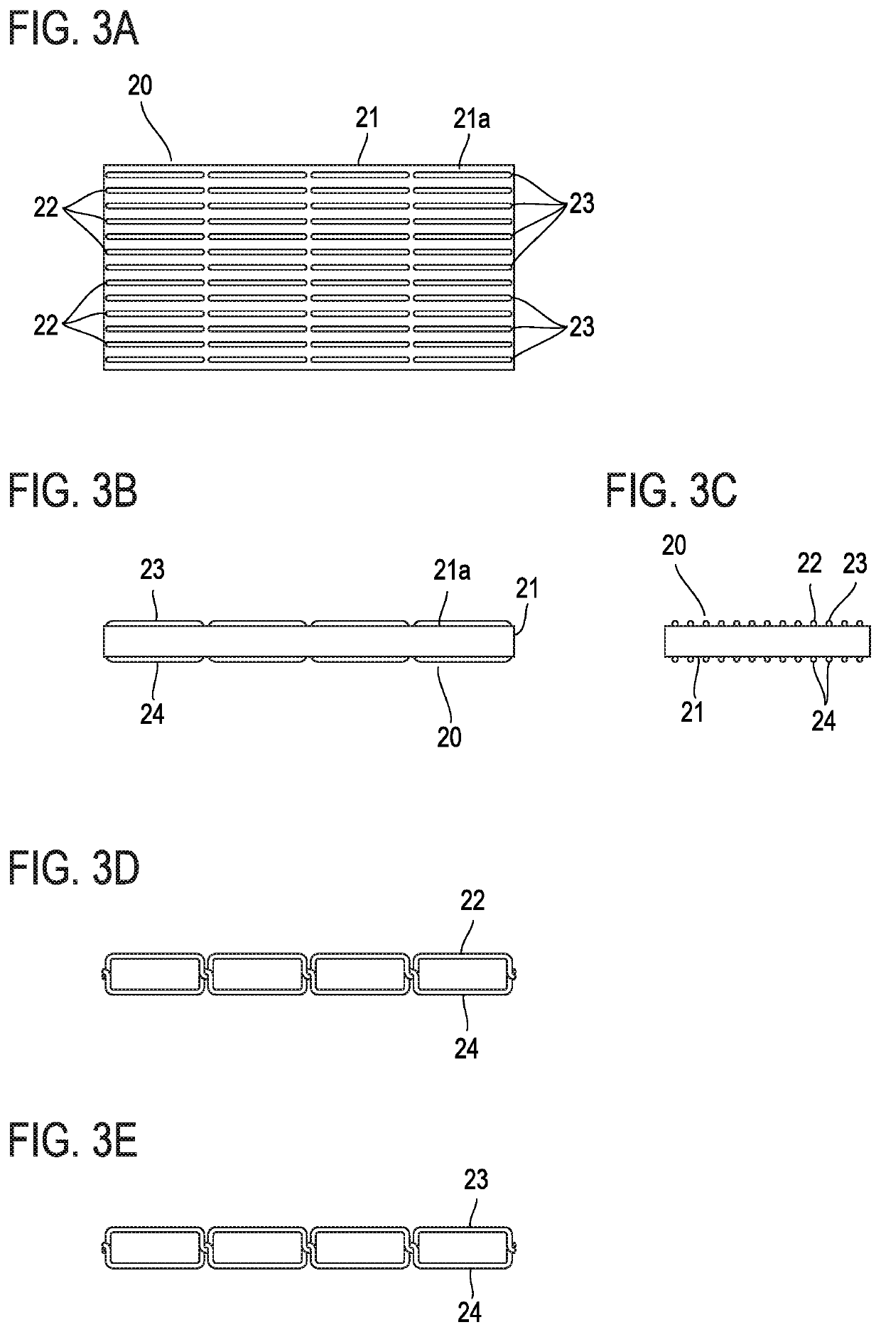
[0068]FIGS. 3A to 3E illustrate the structure of an electrical connecting element according to a first embodiment. An electrical connecting element 20 in this example has the structure in which two or more conductive threads 22 and two or more resin threads 23 having thermal adhesiveness are sewn to a stretchable insulation sheet 21 by a sewing machine.
[0069]The conductive threads 22 are sewn in the longitudinal direction of the rectangular insulation sheet 21 across the whole length of the insulation sheet 21. The conductive threads 22 are disposed in parallel with each other at a predetermined pitch in the width direction of the insulation sheet 21.
[0070]The resin threads 23 are sewn to the insulation sheet 21 on one surface 21a of the insulation sheet 21 without overlapping with any of the conductive threads 22 and both the conductive threads 22 and the resin threads 23 are present on one surface 21a of the insulation sheet 21. In this example, the resin threads 23 are sewn in th...
second embodiment
[0083]FIGS. 6A to 6E illustrate the structure of an electrical connecting element according to a second embodiment. An electrical connecting element 50 is different from the electrical connecting element 20 according to the first embodiment in that the electrical connecting element 50 does not have the resin threads 23 with thermal adhesiveness and includes a thermoplastic adhesive layer 25 with stretchiness formed on one surface 21a of the insulation sheet 21.
[0084]The conductive threads 22 are sewn to a composite sheet 51 including the insulation sheet 21 and the adhesive layer 25, in the same manner as in the first embodiment. That is, the conductive threads 22 are sewn in the longitudinal direction of the rectangular composite sheet 51 across the whole length of the composite sheet 51. The conductive threads 22 are located on the adhesive layer 25. The conductive threads 22 are disposed in parallel with each other at a predetermined pitch in the width direction of the composite ...
third embodiment
[0087]FIG. 9 illustrates the structure of an electrical connecting element according to a third embodiment. An electrical connecting element 60 is different from the electrical connecting element 20 according to the first embodiment in that the conductive threads 22 are set as the upper threads and the lower threads in the sewing machine as illustrated in FIG. 9D when the conductive threads 22 are sewn with the sewing machine, and the resin threads 23 are set as the upper threads and the lower threads in the sewing machine as illustrated in FIG. 9E when the resin threads 23 are sewn with the sewing machine.
[0088]The conductive threads 22 as the upper threads are located on, for example, one surface 21a of the insulation sheet 21 and the conductive threads 22 as the lower threads are located on, for example, the other surface 21b of the insulation sheet 21. In this example, the conductive threads 22 as upper threads and the conductive threads 22 as lower threads are electrically conn...
PUM
| Property | Measurement | Unit |
|---|---|---|
| electrical | aaaaa | aaaaa |
| conductive | aaaaa | aaaaa |
| stretchable | aaaaa | aaaaa |
Abstract
Description
Claims
Application Information
 - R&D Engineer
- R&D Manager
- IP Professional
- Industry Leading Data Capabilities
- Powerful AI technology
- Patent DNA Extraction
Browse by: Latest US Patents, China's latest patents, Technical Efficacy Thesaurus, Application Domain, Technology Topic, Popular Technical Reports.
© 2024 PatSnap. All rights reserved.Legal|Privacy policy|Modern Slavery Act Transparency Statement|Sitemap|About US| Contact US: help@patsnap.com


