Capacitor array, composite electronic component, method for manufacturing capacitor array, and method for manufacturing composite electronic component

a capacitor array and composite electronic technology, applied in the manufacture of capacitors, electrolytic capacitors, capacitor dielectric layers, etc., can solve the problems of increasing mounting costs and achieve the effect of increasing mounting costs

Active Publication Date: 2021-03-18
MURATA MFG CO LTD
View PDF0 Cites 0 Cited by
  • Summary
  • Abstract
  • Description
  • Claims
  • Application Information

AI Technical Summary

Benefits of technology

The technical effect of the invention is to offer a capacitor array that can have multiple solid electrolytic capacitor elements integrated within it.

Problems solved by technology

The plurality of solid electrolytic capacitor elements also require mounting multiple times, and thus causes an increase in the mounting cost.

Method used


Image

  • Capacitor array, composite electronic component, method for manufacturing capacitor array, and method for manufacturing composite electronic component
  • Capacitor array, composite electronic component, method for manufacturing capacitor array, and method for manufacturing composite electronic component
  • Capacitor array, composite electronic component, method for manufacturing capacitor array, and method for manufacturing composite electronic component

Examples


first embodiment

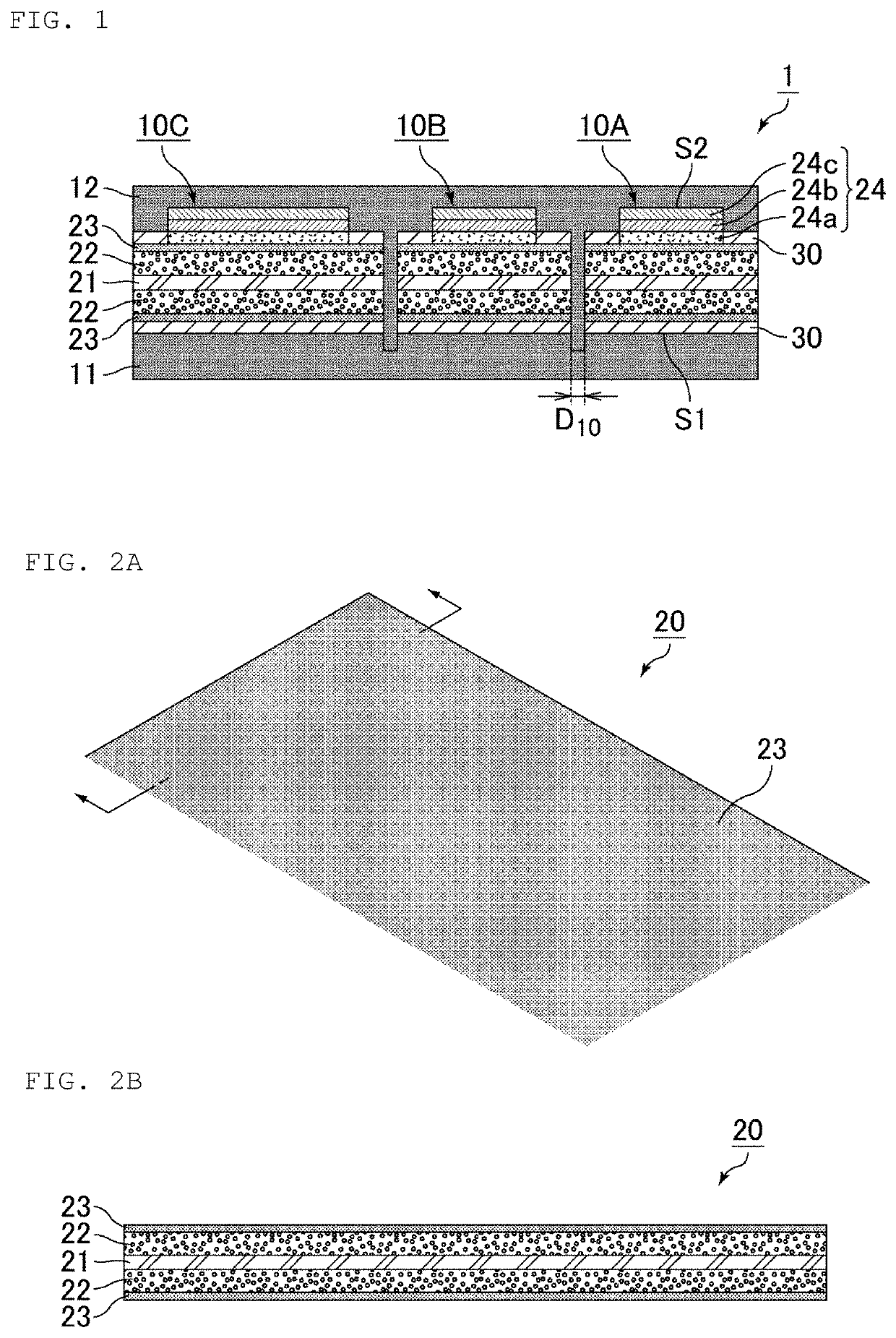
[0052]A capacitor array according to a first embodiment of the present invention is configured such that a second sealing layer extends toward a first sealing layer and into a gap between anode plates of adjacent solid electrolytic capacitor elements of the plurality of solid electrolytic capacitor elements, and further extends into part of the first sealing layer. The above structure improves adhesion between the first sealing layer and the second sealing layer and the capacitor array is thus improved in reliability.

[0053]The capacitor array of the present invention includes the first sealing layer and the second sealing layer each of which contains a sealing resin such as epoxy resin or phenol resin. To prevent the sealing layers from applying stress to an element portion when the capacitor array is formed and thermal stress is loaded, Tg and the modulus of elasticity of each of the sealing layers need to be controlled. Specifically, the sealing layers are each preferably well fil...

second embodiment

[0110]A capacitor array according to a second embodiment of the present invention is configured such that a plurality of element housing spaces are provided on the first sealing layer, and solid electrolytic capacitor elements are disposed in the respective element housing spaces.

[0111]FIG. 18 is a sectional view schematically illustrating an example of the capacitor array according to the second embodiment of the present invention. FIG. 18 illustrates a capacitor array 2 that includes a plurality of solid electrolytic capacitor elements 10A and 10B, a first sealing layer 11 in a sheet-like shape, and a second sealing layer 12 in a sheet-like shape. The solid electrolytic capacitor element 10A has a first main surface S1 and a second main surface S2 facing each other in a thickness direction (top-bottom direction in FIG. 18), and the first main surface S1 is disposed on the first sealing layer 11. The same applies to the solid electrolytic capacitor element 10B. The second sealing l...


PUM


Abstract

A capacitor array that includes a plurality of solid electrolytic capacitor elements each of which has a first main surface and a second main surface facing each other in a thickness direction and includes an anode plate made of a valve action metal, a porous layer on at least one surface of the anode plate, a dielectric layer on a surface of the porous layer, and a cathode layer on a surface of the dielectric layer and including a solid electrolyte layer; a first sealing layer in a sheet-like shape and covering the first main surface of the plurality of solid electrolytic capacitor elements; and a second sealing layer in a sheet-like shape and covering the second main surface of the plurality of solid electrolytic capacitor elements.

Description

CROSS REFERENCE TO RELATED APPLICATIONS[0001]The present application is a continuation of International application No. PCT / JP2019 / 021936, filed Jun. 3, 2019, which claims priority to Japanese Patent Application No. 2018-111162, filed Jun. 11, 2018, the entire contents of each of which are incorporated herein by reference.FIELD OF THE INVENTION[0002]The present invention relates to a capacitor array, a composite electronic component, a method for manufacturing a capacitor array, and a method for manufacturing a composite electronic component.BACKGROUND OF THE INVENTION[0003]A solid electrolytic capacitor typically includes a solid electrolytic capacitor element having an anode plate made of a valve action metal such as aluminum, a porous layer on a main surface of the anode plate, a dielectric layer on a surface of the porous layer, and a cathode layer on a surface of the dielectric layer and including a solid electrolyte layer.[0004]Patent Document 1 discloses a solid electrolytic ...

Claims


Application Information

Patent Timeline
IPC IPC(8): H01G9/10H01G9/15H01G9/042H01G9/07H01G2/10H01G9/26H01G9/28H01G9/00
CPCH01G9/10H01G9/15H01G9/042H01G9/07H01G9/0036H01G9/26H01G9/28H01G9/0032H01G2/106H01G2/02H01G9/08H01G9/048H01G9/0029
Inventor FURUKAWA, TAKESHIMIYAKE, MISATO
Owner MURATA MFG CO LTD
Why Eureka
Try Eureka