

Blowby gas circulating apparatus for an internal combustion engine
- Summary
- Abstract
- Description
- Claims
- Application Information
AI Technical Summary
Benefits of technology
Problems solved by technology
Method used
Image

Examples
Embodiment Construction
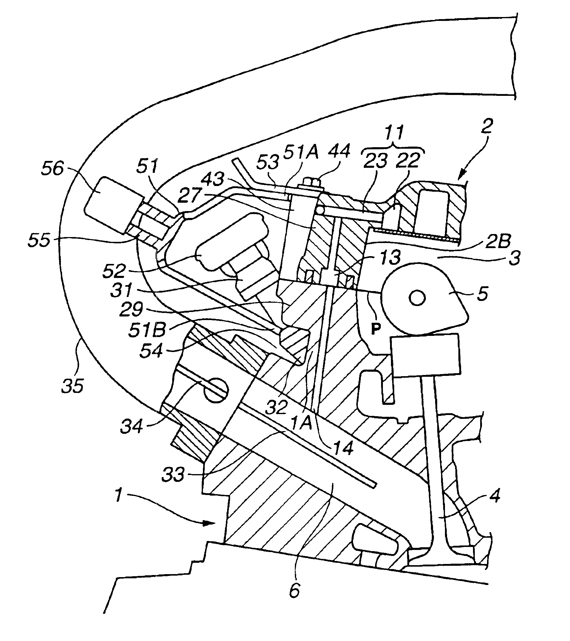
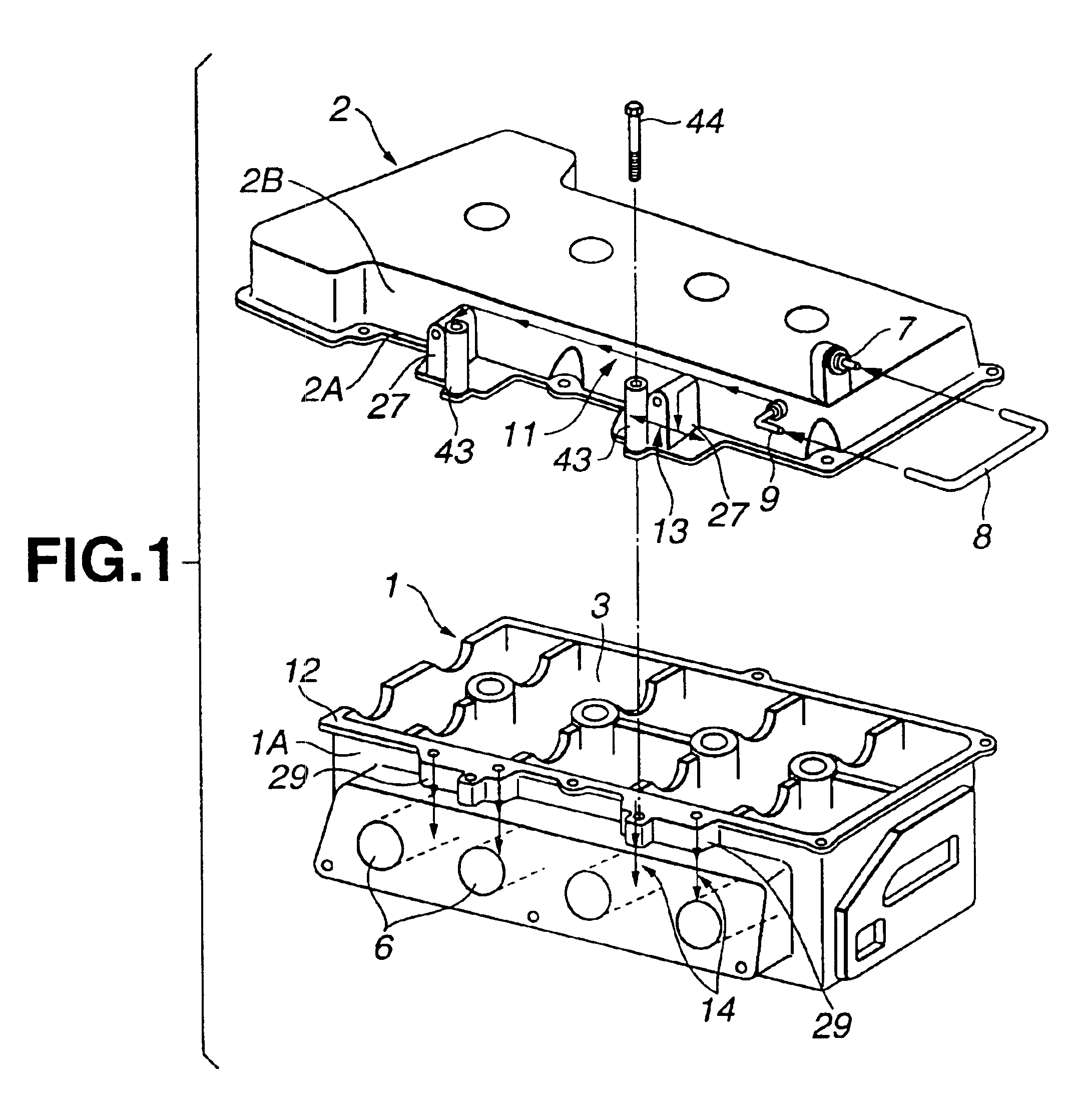
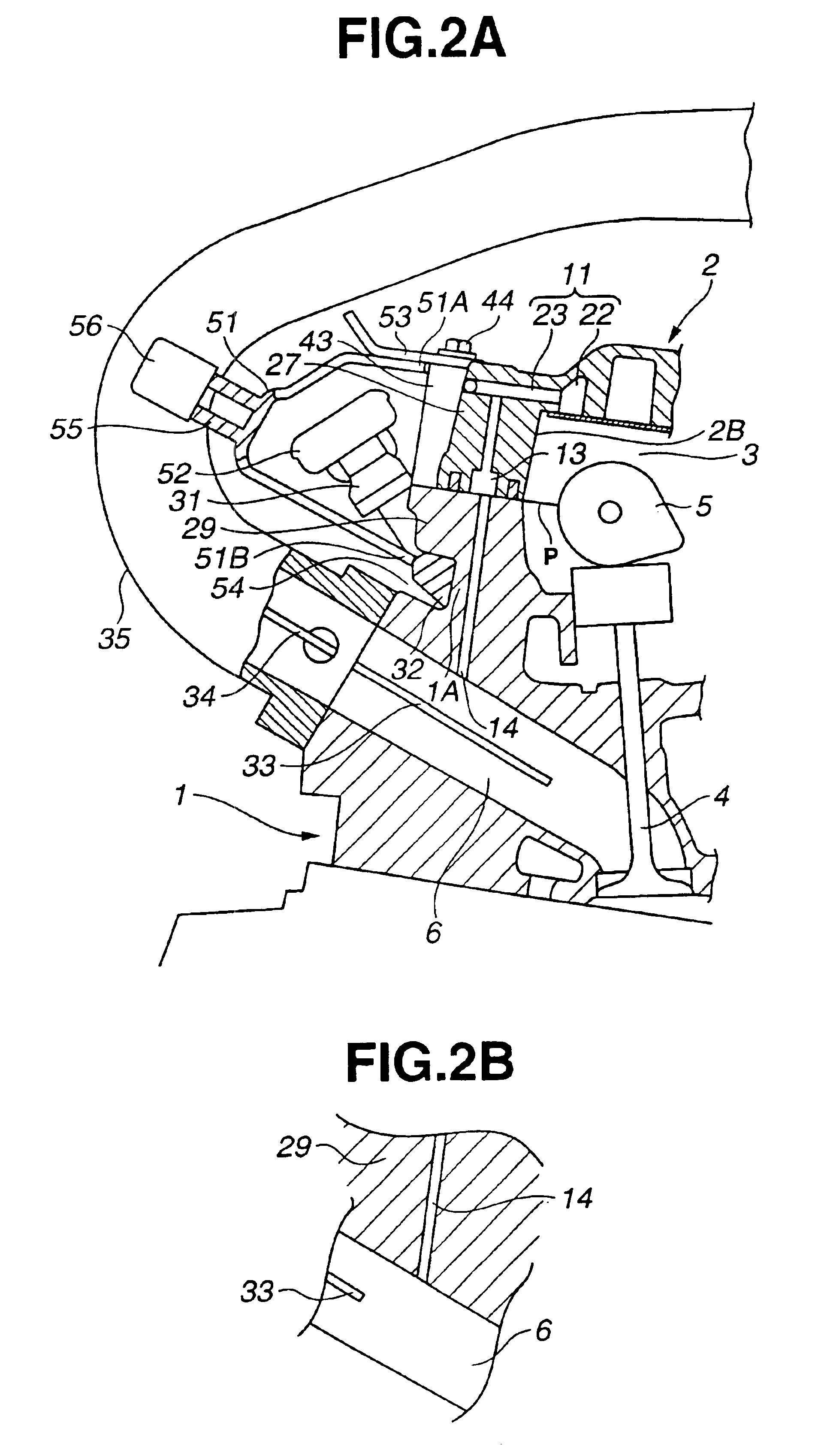
[0022]Referring to FIGS. 1 to 8, a blowby gas circulating apparatus according to an embodiment of the present invention now is explained. In this embodiment, the blowby gas circulating apparatus is applied to an in-line four-cylinder internal combustion engine of a vehicle. The blowby gas circulating apparatus has a blowby gas path formed in cylinder head 1 and cylinder head cover 2 as indicated by a series of arrows in FIG. 1. Cylinder head 1 has an upper opening on an upper side thereof. Cylinder head cover 2 has a lower opening on a lower side thereof. As illustrated in FIG. 2A, cylinder head cover 2 is so disposed as to cover the upper opening of cylinder head 1 and cooperate with cylinder head 1 to define valve chamber 3 in which intake camshaft 5 for driving intake valve 4 is accommodated together with an exhaust camshaft, not shown. A blowby gas flowing from a crankcase, not shown, into valve chamber 3 is circulated to an intake system, specifically, to intake port 6 of each ...
PUM
| Property | Measurement | Unit |
|---|---|---|
| Flow rate | aaaaa | aaaaa |
Abstract
Description
Claims
Application Information