
LED chip structure, manufacturing method thereof, and mass transfer method applying the LED chip structure

a technology of led chips and manufacturing methods, applied in the field of semiconductor technology, can solve the problems of increasing the difficulty of mass transfer and uneasy transfer of chips during the manufacturing process, and achieve the effects of simple and convenient manufacturing processes, good use, and easy completion

Inactive Publication Date: 2021-03-25
DONGGUAN INST OF OPTO ELECTRONICS PEKING UNIV
View PDF0 Cites 0 Cited by
  • Summary
  • Abstract
  • Description
  • Claims
  • Application Information

AI Technical Summary

Benefits of technology

The present invention provides an LED chip structure, its manufacturing method, and a mass transfer method applying the LED chip structure. The LED chip structure has reasonable design and convenient transfer, while the manufacturing method has the features of simple manufacture process, easy manufacture, and compact LED chip structure. The mass transfer method applying the LED chip structure has the features of simple operation, easy alignment, and convenient transfer. The main technical effects of this patent include avoiding the specific identification of the electrodes of the LED chips during the mass transfer process and reducing the level of difficulty of alignment to facilitate the transfer of the LED chips. The LED chip structure is compact and good to use, and the mass transfer method is convenient for transferring a large quantity of LED chips.

Problems solved by technology

In view of the relatively small size of the micro LED chips, it is uneasy to transfer the chips during the manufacturing process.
In addition, the level of difficulty of the mass transfer is further increased when the electrode alignment of the micro LED chips is taken into account.

Method used


Image

  • LED chip structure, manufacturing method thereof, and mass transfer method applying the LED chip structure
  • LED chip structure, manufacturing method thereof, and mass transfer method applying the LED chip structure
  • LED chip structure, manufacturing method thereof, and mass transfer method applying the LED chip structure

Examples


Embodiment Construction

[0031]The technical characteristics of the present invention will become apparent with the detailed description of preferred embodiments accompanied with the illustration of related drawings.

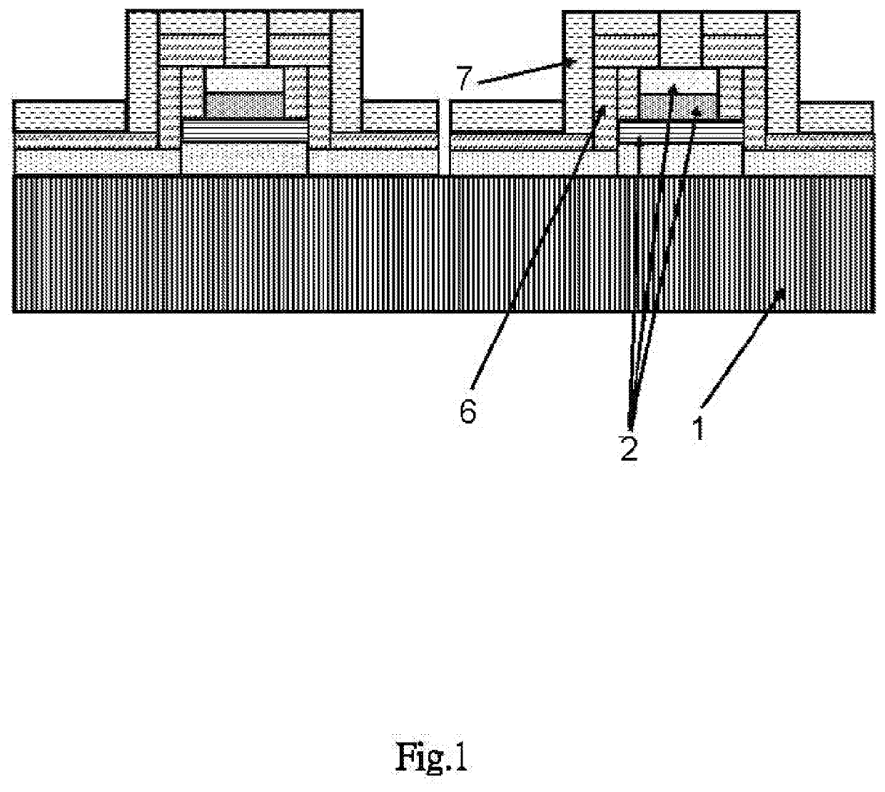
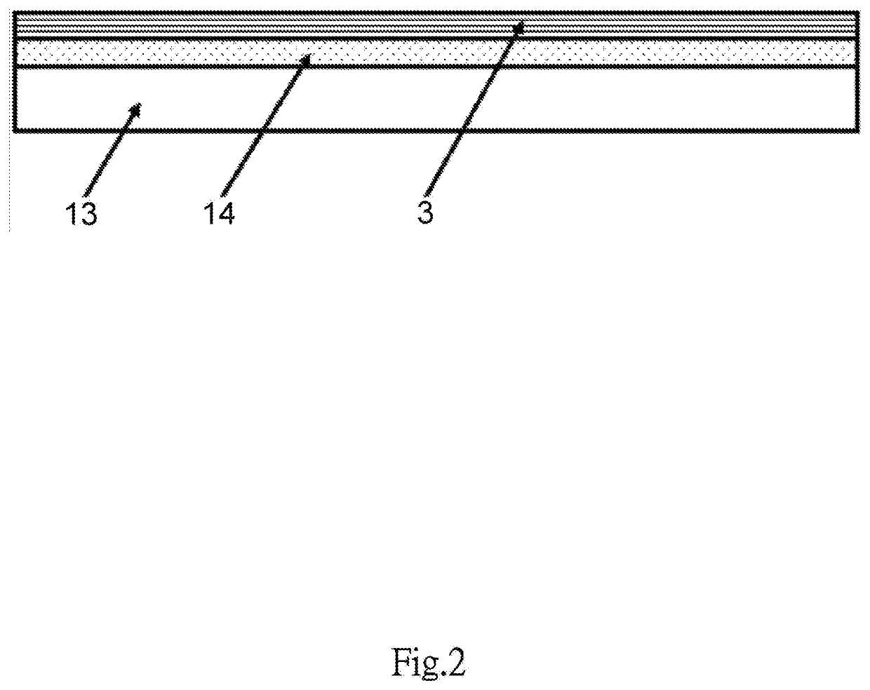
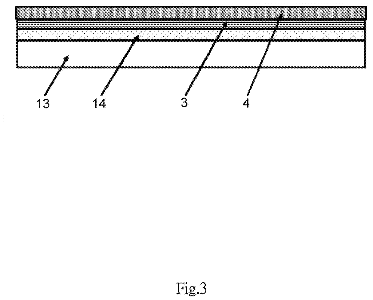
[0032]With reference to FIGS. 1 to 10 for an LED chip structure in accordance with an embodiment of the present invention, the LED chip structure comprises a substrate, a light emitting unit 2 coupled to the substrate, a passivation layer 6, an ohmic contact layer 7, and a metal layer 5 disposed at the junction of the light emitting unit 2 and the substrate, wherein the passivation layer 6 is disposed around the periphery of the light emitting unit 2 and coupled to the metal layer 5, and the ohmic contact layer 7 is covered onto the passivation layer 6 and coupled to the light emitting unit 2. The LED chip structure has a reasonable design of covering the ohmic contact layer 7 on the outside of the structure, so as to avoid the specific identification of the electrodes of the LED chips during th...


PUM


Abstract

Disclosed are an LED chip structure and its manufacturing method, and a mass transfer method applying the LED chip structure. The LED chip structure includes a substrate, a light emitting unit connected to the substrate, a passivation layer, an ohmic contact layer, and a metal layer formed at the junction of the light emitting unit and the substrate. The passivation layer surrounds the periphery of the light emitting unit and is connected to the metal layer, and the ohmic contact layer is covered onto the passivation layer and connected to the light emitting unit. The LED chip structure has the features of reasonable design and convenient transfer; the manufacturing method has the features of simple manufacture process, easy manufacture, and compact LED chip structure; and the mass transfer method applying the LED chip structure has the features of simple operation, easy alignment, and convenient transfer.

Description

FIELD OF THE INVENTION[0001]The present invention relates to the semiconductor technology, and more particularly to an LED chip structure and its manufacturing method, and a mass transfer method applying the LED chip structure.BACKGROUND OF THE INVENTION[0002]Light emitting diode (LED) with the advantages of small volume, low power, long service life, high brightness and active light emission is widely used in the areas of illumination and display. Micro LED, also known as mini LED, mLED or μLED, is a novel tablet display technology. Compared with the popular liquid crystal display device, the micro LED display device having an LED array with independent primitive components has better contrast, faster response speed and lower power consumption.[0003]Since the micro LED is manufactured individually, therefore it is necessary to transfer a very large amount of micro LED chips onto a substrate in the manufacturing process of the display devices. At present, the conventional mass trans...

Claims


Application Information

Patent Timeline
IPC IPC(8): H01L33/62H01L25/075H01L33/00
CPCH01L33/62H01L25/0753H01L2933/0066H01L33/0093H01L33/0091H01L33/38H01L33/44H01L33/0066H01L33/0075H01L27/156H01L2933/0016H01L2933/0025H01L33/0095H01L2933/005H01L33/52
Inventor LI, CHENGMINGWANG, QIZHANG, GUOYI
Owner DONGGUAN INST OF OPTO ELECTRONICS PEKING UNIV
Learn More