
Methods and apparatus for reception of low photon density optical signals

a low-density optical and signal technology, applied in the field of low-density optical signal reception methods and apparatuses, can solve the problems achieve the effects of reducing the detectability of free space optical transmissions, extending the range of deep space communication, and improving the sensitivity of optical receivers

Active Publication Date: 2021-04-01
RAYTHEON CO
View PDF0 Cites 16 Cited by
  • Summary
  • Abstract
  • Description
  • Claims
  • Application Information

AI Technical Summary

Benefits of technology

This patent describes a way to make optical receivers better and to make it harder to detect optical signals in space. This can be used to improve the range of deep space communications and make it harder for people to see optical signals. The methods described can work with different types of optical signals and are independent of how they are modulated.

Problems solved by technology

In addition, further aspects and embodiments provide methods and apparatus that reduce the detectability of free space optical transmissions.

Method used


Image

  • Methods and apparatus for reception of low photon density optical signals
  • Methods and apparatus for reception of low photon density optical signals
  • Methods and apparatus for reception of low photon density optical signals

Examples


Embodiment Construction

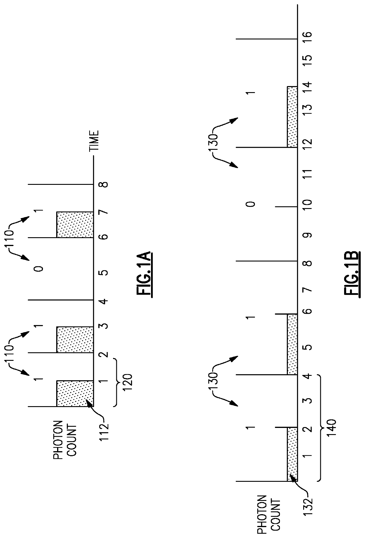
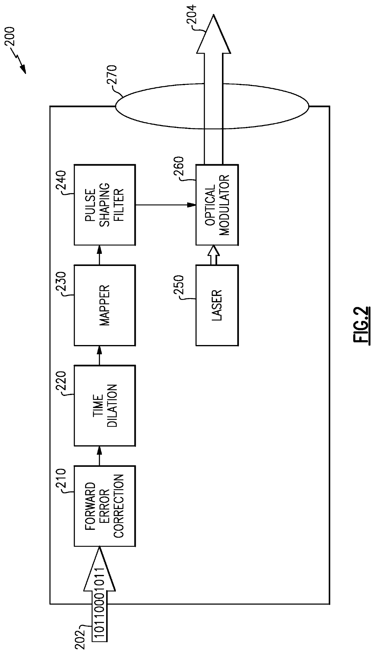
[0039]Certain aspects and embodiments are directed to methods and apparatus for reducing the detectability of free space optical transmissions using time dilation of the encoded symbols. Similar to the way spread spectrum signals spread a fixed amount of energy over a broad range of frequencies to reduce the power spectral density, according to certain embodiments, each symbol in an encoded transmission is spread over a large time interval, thereby reducing the photon density, which may make detection of the transmission more difficult. Certain embodiments are directed to an optical transmitter configured to emit a modulated optical signal encoded with time-dilated symbols. Further embodiments are directed to an optical receiver capable of detecting and demodulating the modulated optical signal. In addition, as discussed further below, certain aspects and embodiments provide an optical receiver with improved sensitivity to allow for reception / detection of very weak optical signals.

[...


PUM

PropertyMeasurementUnit
phaseaaaaaaaaaa
electricalaaaaaaaaaa
photon-densityaaaaaaaaaa

Abstract

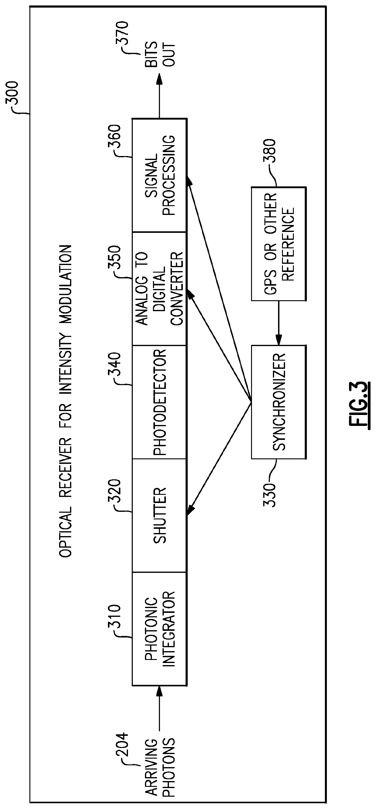
An optical receiver includes a photonic integrator configured to accumulate optical signal energy corresponding to the input optical signal during an integration period, and to produce an output optical signal at an end of the integration period, the output optical signal having a higher intensity than the input optical signal, a shutter operable between a closed position and an open position, the shutter configured to prevent the output optical signal from exiting the photonic integrator when in the closed position and to allow the output optical signal to exit the photonic integrator when in the open position, a synchronizer coupled to the shutter and configured to control the shutter between the open position and the closed position; and a photodetector configured to receive the output optical signal when the shutter is in the open position and to produce an electrical signal corresponding to the output optical signal.

Description

CROSS-REFERENCE TO RELATED APPLICATIONS[0001]This application claims priority under 35 USC § 119(e) to U.S. Provisional Patent Application Serial No. 62 / 906,487, titled “METHODS AND APPARATUS FOR TRANSMISSION AND DETECTION OF LOW PHOTON DENSITY OPTICAL SIGNALS,” filed Sep. 26, 2019, and U.S. Provisional Patent Application Serial No. 62 / 906,490, titled “METHODS AND APPARATUS FOR TRANSMISSION AND DETECTION OF LOW PHOTON DENSITY OPTICAL SIGNALS,” filed Sep. 26, 2019, both of which are hereby incorporated by reference in their entirety for all purposes.BACKGROUND[0002]There are many applications in which it may be desirable to conceal transmission of a communications signal. Free space optical communications is a relatively secure communications method when compared to radio frequency communications. The security largely comes from the narrow beam width of an optical transmission. However, with the appropriate equipment, optical signals can be detected and intercepted. For example, opti...

Claims


Application Information

Patent Timeline
Patent Type & Authority Applications(United States)
IPC IPC(8): H04B10/60G02B17/00G02F1/137
CPCH04B10/60G02F1/137G02B17/004G02F2203/50G02F1/213G02F1/0121H04B10/70H04B10/112H04B10/541H04B10/5561H04B10/66H04B10/516
Inventor GRACEFFO, GARY M.KOWALEVICZ, ANDREWDOLGIN, BENJAMIN P.
Owner RAYTHEON CO
Learn More