Bandpass filter and method for increasing the sensitivity on reception of an optical signal

a technology of optical receiver and sensitivity, applied in the field of bandpass filter and method for increasing the sensitivity on reception of optical signals, can solve the problems of unsatisfactory optical receiver, limited bandwidth of electronic processing, inability to read correctly, etc., and achieve the effect of increasing the sensitivity of optical receivers and very effective sensitivity

Inactive Publication Date: 2008-03-25
XIEON NETWORKS SARL
View PDF5 Cites 0 Cited by
  • Summary
  • Abstract
  • Description
  • Claims
  • Application Information

AI Technical Summary

Benefits of technology

[0009]A further advantage of the present invention is that the use of the bandpass filter makes possible an effective method for increasing the sensitivity of an optical receiver for a data signal at an optical carrier frequency. Increasing the sensitivity is very effective particularly if the optical receiver has a wide decision window.
[0010]It goes without saying that the present invention also is suitable for low-bit-rate data signals as in the case of electrical signals, in which case the bandpass filter should be in the form of an electronic unit, for example. It follows from this that the bandpass filter according to the present invention may be implemented for any desired bit rates.

Problems solved by technology

A receiver of this type is not ideal, in practice; that is, the bandwidth of electronic processing is limited.
High-bit-rate data in the received signal, thus is not read correctly.

Method used


Image

  • Bandpass filter and method for increasing the sensitivity on reception of an optical signal
  • Bandpass filter and method for increasing the sensitivity on reception of an optical signal
  • Bandpass filter and method for increasing the sensitivity on reception of an optical signal

Examples


Embodiment Construction

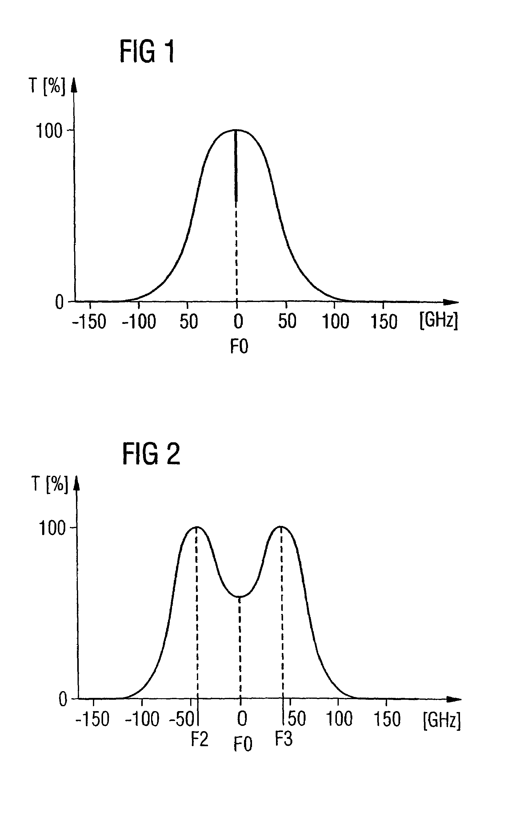
[0016]FIG. 1 shows a first transmission curve T of a bandpass filter according to the present invention having a passband Δf around a mid-frequency F0 which corresponds to a carrier frequency F1 for a data signal to be filtered. The mid-frequency F0 is preferably 0 Hz here, but in practice occurs in the optical or radio-frequency band. The transmission curve T has an attenuation range which occurs substantially at the mid-frequency F0. In the present example, the attenuation range is narrowband and steep. In theory, the attenuation range may be described using a pulsed function, but should not give rise to any sudden interfering phase changes in the optical filtered data signal. If need be, a linear phase shift could be allowed in the filtered data signal. A high-order IIR filter, inter alia, may be used to implement the bandpass filter according to the present invention.

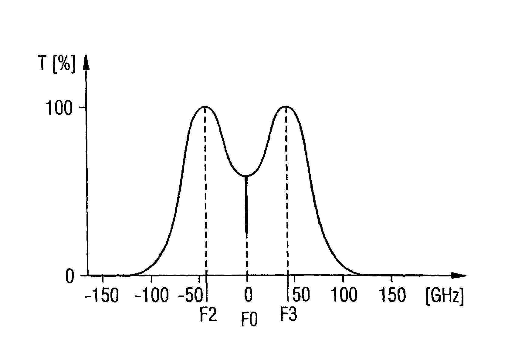
[0017]FIG. 2 shows a second transmission curve T of the bandpass filter according to the present invention. The a...


PUM


Abstract

A bandpass filter, and associated method, are provided for an optical data signal, wherein the transmission curve of the bandpass filter has a passband at a mid-frequency for a particular bandwidth. The transmission curve has an attenuation range which covers the mid-frequency. This makes it possible to effectively increase the sensitivity of optical reception, particularly at a high data rate. When use is made of a number of bandpass filters having passbands which are arranged next to one another spectrally, such arrangement is highly suitable for a WDM signal.

Description

BACKGROUND OF THE INVENTION[0001]The transmission capacity of optical wavelength division multiplexed channels in a WDM transmission system can be increased by reducing the frequency separation between the individual optical channels. The spectral efficiency of the transmission system increases with a continual reduction in the frequency separation and simultaneous increase in the channel data rate. At the same time, the demands imposed on the optical filters which separate the individual optical channels from one another also increase. On the one hand, such optical filters must allow the wanted signal to pass unimpeded as far as possible but, on the other hand, interference from the adjacent channels should be suppressed as efficiently as possible.[0002]An optical channel selected in this manner arrives at a receiver which converts the amplitude-modulated light to a sequence of electrical pulses. A receiver of this type is not ideal, in practice; that is, the bandwidth of electroni...

Claims


Application Information

Patent Timeline
Patent Type & Authority Patents(United States)
IPC IPC(8): G02B6/26H04B10/67
CPCH04B10/675
Inventor ROHDE, HARALD
Owner XIEON NETWORKS SARL
Why Eureka
Try Eureka