
Chip package and manufacturing method thereof

a technology of chip package and manufacturing method, which is applied in the direction of semiconductor devices, electrical equipment, semiconductor/solid-state device details, etc., can solve the problems of damage to the chip package, prone to warpage of the film, and the thickness of the translucent film is not specifically designed, so as to improve the reliability of the chip package

Active Publication Date: 2021-04-08
XINTEC INC
View PDF0 Cites 0 Cited by
  • Summary
  • Abstract
  • Description
  • Claims
  • Application Information

AI Technical Summary

Benefits of technology

The present invention relates to a new method of bonding layers in a semiconductor chip package. The method involves using a material called benzocyclobutene (BCB) as the bonding layer. This bonding layer can be applied to the lower substrate and / or the first silicon nitride substrate through coating and can fill the space between them after bonding. Additionally, the bonding layer does not absorb water, which helps prevent moisture from entering the chip package and improves its reliability.

Problems solved by technology

This makes a cavity between the chip and the lower translucent film, and may create moisture in the cavity, thus damaging the chip package.
Moreover, film thickness of the translucent film is not specifically designed.
Therefore, the film is prone to warpage caused by film stress.
Furthermore, the location of the dummy pad of the chip package is also not specifically designed.
This may cause a capacitance effect, and electrostatic and electrical stress may deconstruct the chip package.
The issues put above make it difficult to improve product reliability.
Moreover, the bonding layer is not water-absorbing.

Method used


Image

  • Chip package and manufacturing method thereof
  • Chip package and manufacturing method thereof
  • Chip package and manufacturing method thereof

Examples


Embodiment Construction

[0035]Reference will now be made in detail to the present embodiments of the invention, examples of which are illustrated in the accompanying drawings. Wherever possible, the same reference numbers are used in the drawings and the description to refer to the same or like parts.

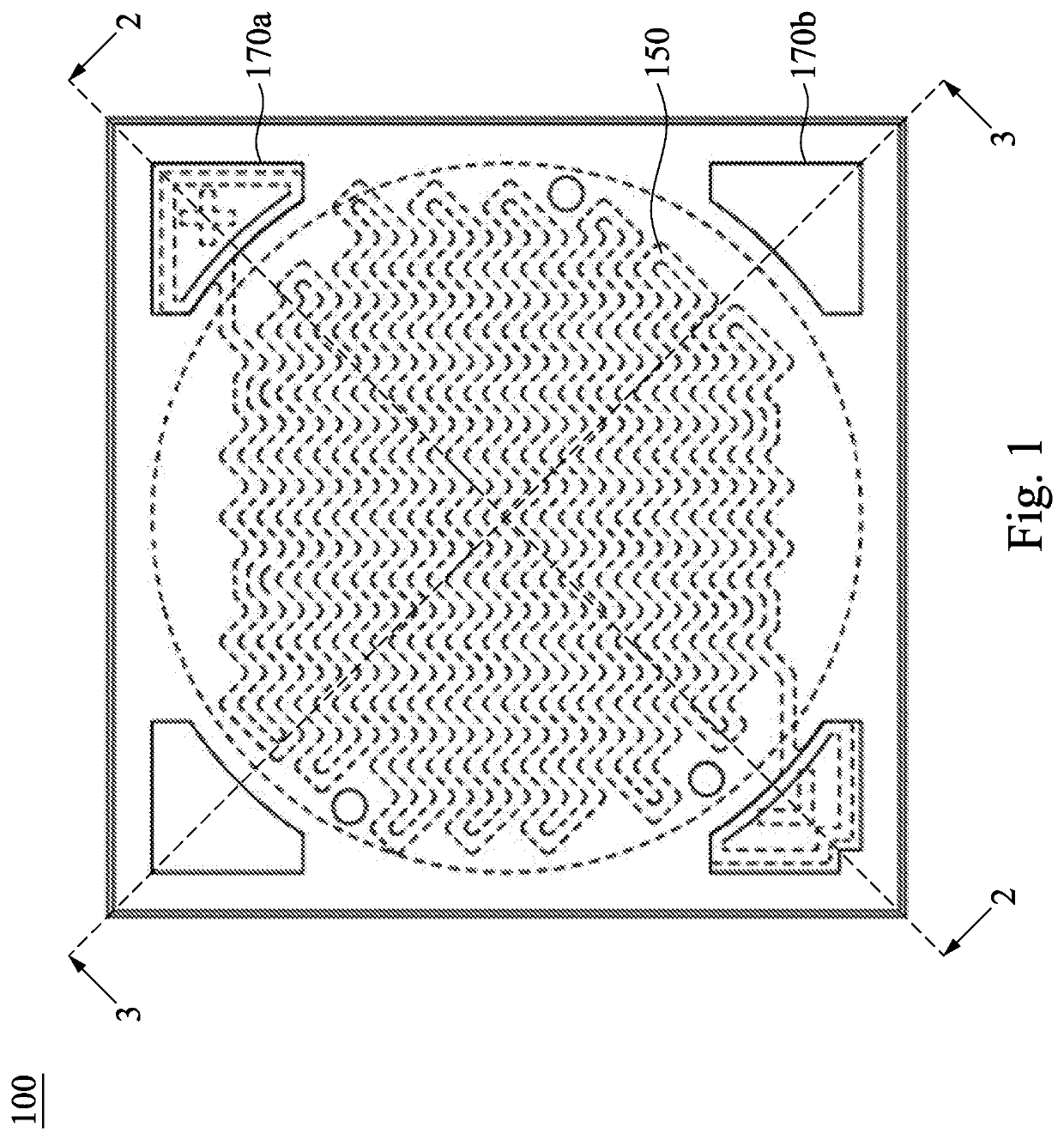
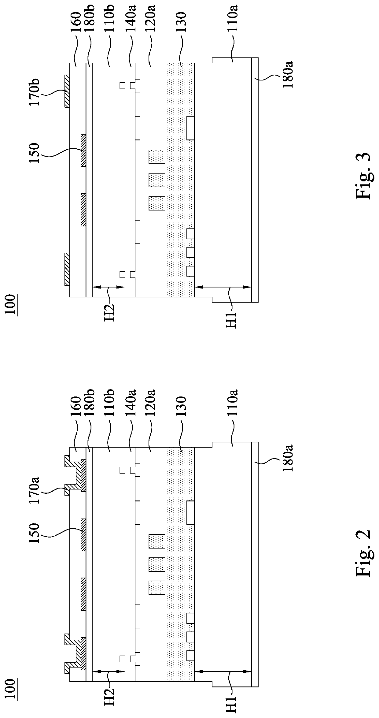
[0036]FIG. 1 is a top view of a chip package 100 according to one embodiment of the present invention. FIG. 2 is a cross-sectional view of the chip package 100 taken along line 2-2 shown in FIG. 1. As shown in FIG. 1 and FIG. 2, the chip package 100 includes a lower substrate 110a, a first silicon nitride substrate 120a, a bonding layer 130, an upper substrate 110b, a first functional layer 140a, a transparent conductive layer 150, an isolation layer 160, and a first conductive pad 170a. The bonding layer 130 is located between the lower substrate 110a and the first silicon nitride substrate 120a, and made of a material comprising Benzocyclobutene (BCB). The bonding layer 130 fills up the space between the low...


PUM

PropertyMeasurementUnit
transparentaaaaaaaaaa
thickness H1aaaaaaaaaa

Abstract

A chip package includes a lower substrate, a first silicon nitride substrate, a bonding layer, an upper substrate, a first functional layer, a transparent conductive layer, an isolation layer, and a first conductive pad. The supporting layer is located between the lower substrate and the first silicon nitride substrate, and is made of a material including Benzocyclobutene (BCB). The upper substrate is located on the first silicon nitride substrate. The first functional layer is located between the upper substrate and the first silicon nitride substrate. The transparent conductive layer is located on the upper substrate. The isolation layer covers the upper substrate and the transparent conductive layer. The first conductive pad is located in the isolation layer and in electrical contact with the transparent conductive layer.

Description

RELATED APPLICATION[0001]This application claims priority to U.S. Provisional Application Ser. No. 62 / 910,171, filed Oct. 3, 2019, which is herein incorporated by reference in its entirety.BACKGROUNDField of Invention[0002]The present invention relates to a chip package and a manufacturing method of the chip package.Description of Related Art[0003]Typically, chip packages used in optics may include chips with functional layers and translucent films set above and below the chip. The chip is bonded with the lower translucent film by a polymer layer with hygroscopic property. The polymer layer has a hollow structure. This makes a cavity between the chip and the lower translucent film, and may create moisture in the cavity, thus damaging the chip package. Moreover, film thickness of the translucent film is not specifically designed. Therefore, the film is prone to warpage caused by film stress. Furthermore, the location of the dummy pad of the chip package is also not specifically desig...

Claims


Application Information

Patent Timeline
Patent Type & Authority Applications(United States)
IPC IPC(8): H01L23/498H01L21/48
CPCH01L23/49833H01L21/4857H01L23/49822H01L23/49811H01L33/48
Inventor SUEN, WEI-LUENLAI, JIUN-YENSHEN, HSING-LUNGLIU, TSANG-YU
Owner XINTEC INC
Learn More