

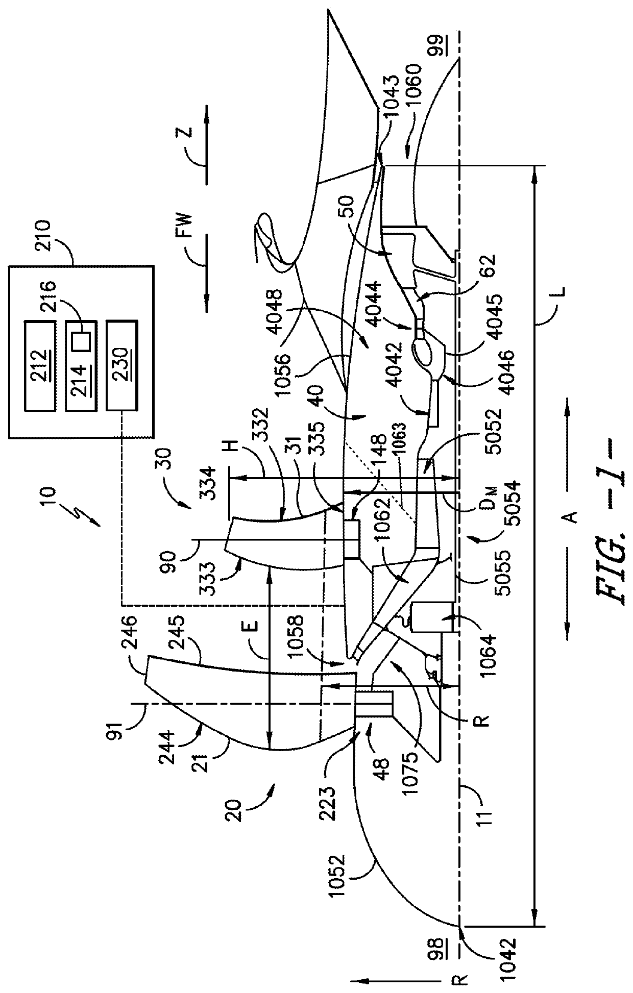
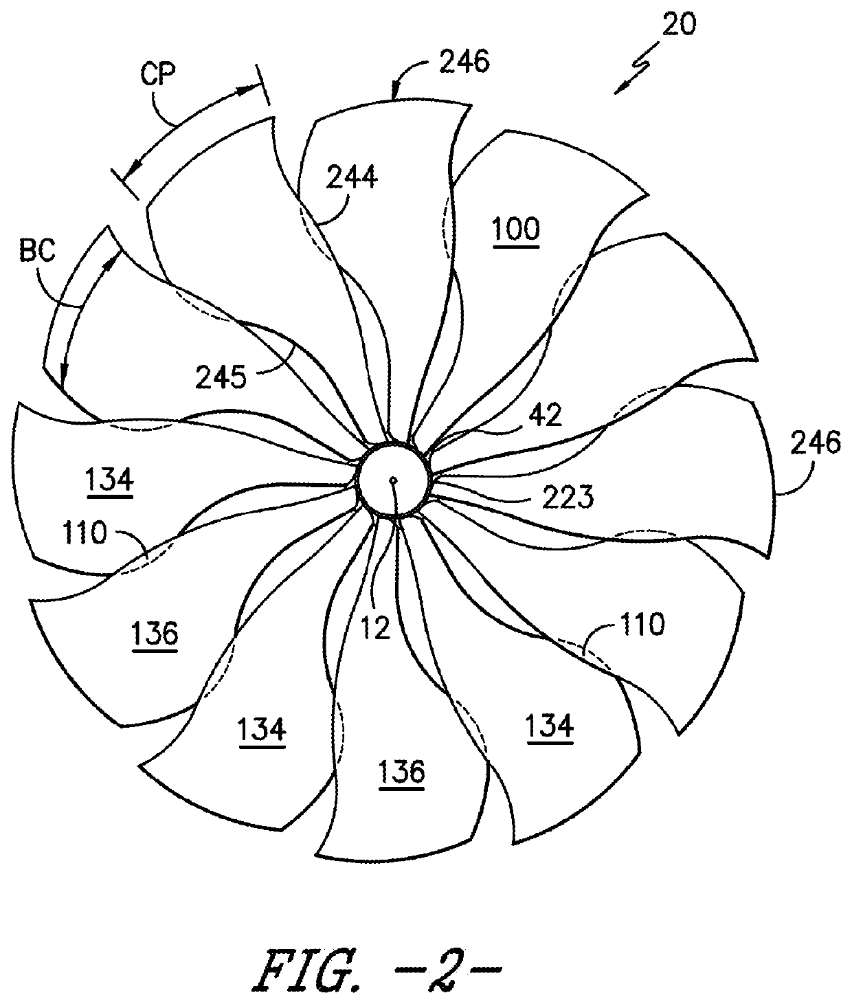
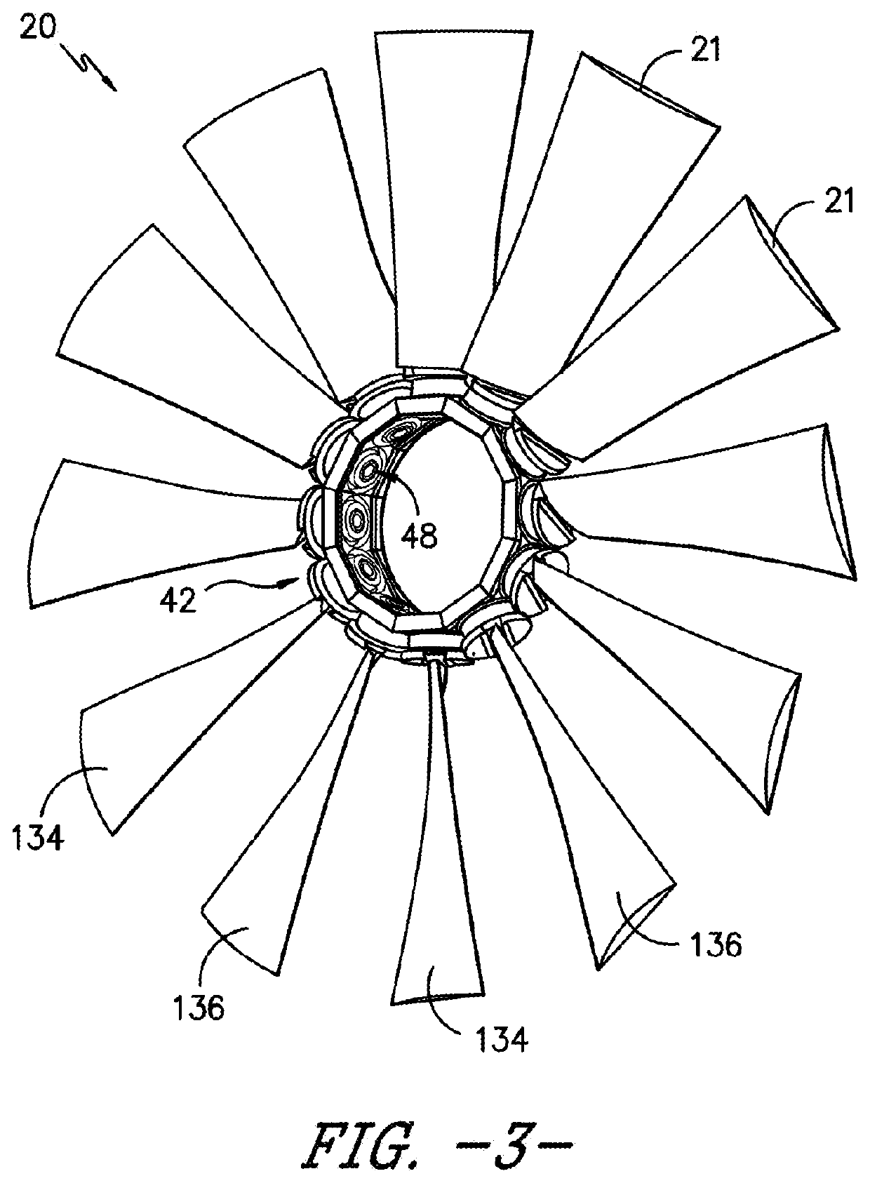
System and method for control for unducted engine
a technology of unducted engine and control system, which is applied in the direction of rotors, machines/engines, other domestic objects, etc., can solve the problems of increasing the size and weight of the nacelle, general limited engine, and presenting technical challenges for the contra-rotating rotor assembly
- Summary
- Abstract
- Description
- Claims
- Application Information
AI Technical Summary
Benefits of technology
Problems solved by technology
Method used
Image

Examples
Embodiment Construction
[0024]Reference will now be made in detail to present embodiments of the invention, one or more examples of which are illustrated in the accompanying drawings. The detailed description uses numerical and letter designations to refer to features in the drawings. Like or similar designations in the drawings and description have been used to refer to like or similar parts of the invention.
[0025]The word “exemplary” is used herein to mean “serving as an example, instance, or illustration.” Any implementation described herein as “exemplary” is not necessarily to be construed as preferred or advantageous over other implementations.
[0026]As used herein, the terms “first”, “second”, and “third” may be used interchangeably to distinguish one component from another and are not intended to signify location or importance of the individual components.
[0027]The terms “forward” and “aft” refer to relative positions within a gas turbine engine or vehicle, and refer to the normal operational attitud...
PUM
 Abstract
Description
Claims
Application Information