
Quick detaching device for handgun tectical light

a technology of tectical lights and detachable devices, which is applied in the direction of lighting and heating equipment, lighting support devices, weapons, etc., can solve the problems of inconvenient user operation, inconvenient design, and the ability to only detach the tactical light, and achieves convenient use, quick mounting and detachment of the tactical light, and high temperature resistance

Active Publication Date: 2021-04-15
SHENZHEN OLIGHT E COMMERCE TECH CO LTD
View PDF0 Cites 4 Cited by
  • Summary
  • Abstract
  • Description
  • Claims
  • Application Information

AI Technical Summary

Benefits of technology

The present invention is a quick detaching device for handgun tactical light. The detachable tactical light can be easily and quickly mounted and detached without the need for tools or effort. The device is made with a spring plate that has high-temperature resistance, anti-friction, and is electrically and heat conductive. The materials used in the device are carbon fiber, ceramic powder, epoxy resin, and polyurethane resin, which make the device strong, durable, and resistant to corrosion. The polyurethane resin used in the spring plate is made with toluene diisocyanate, which increases its anti-abrasive properties. Overall, this invention provides a convenient and efficient way to attain and use a detachable tactical light for handguns.

Problems solved by technology

This kind of design is inconvenient in that the tactical light could only be detached by hand with great strength or with tools.
In outdoor environment where there is no tools or when the user does not have sufficient strength, user operation is very inconvenient and the detaching process takes relatively long time.
When the battery of the tactical light runs out and requires charging, frequency would be higher and the detaching process is troublesome.
It is even more troublesome when the user wishes to use the tactical light as a torch.
This results in increased difficulty in user operation and bad experience.

Method used


Image

  • Quick detaching device for handgun tectical light
  • Quick detaching device for handgun tectical light
  • Quick detaching device for handgun tectical light

Examples


Embodiment Construction

[0027]A preferred embodiment of the present invention is described below with the accompanying drawings.

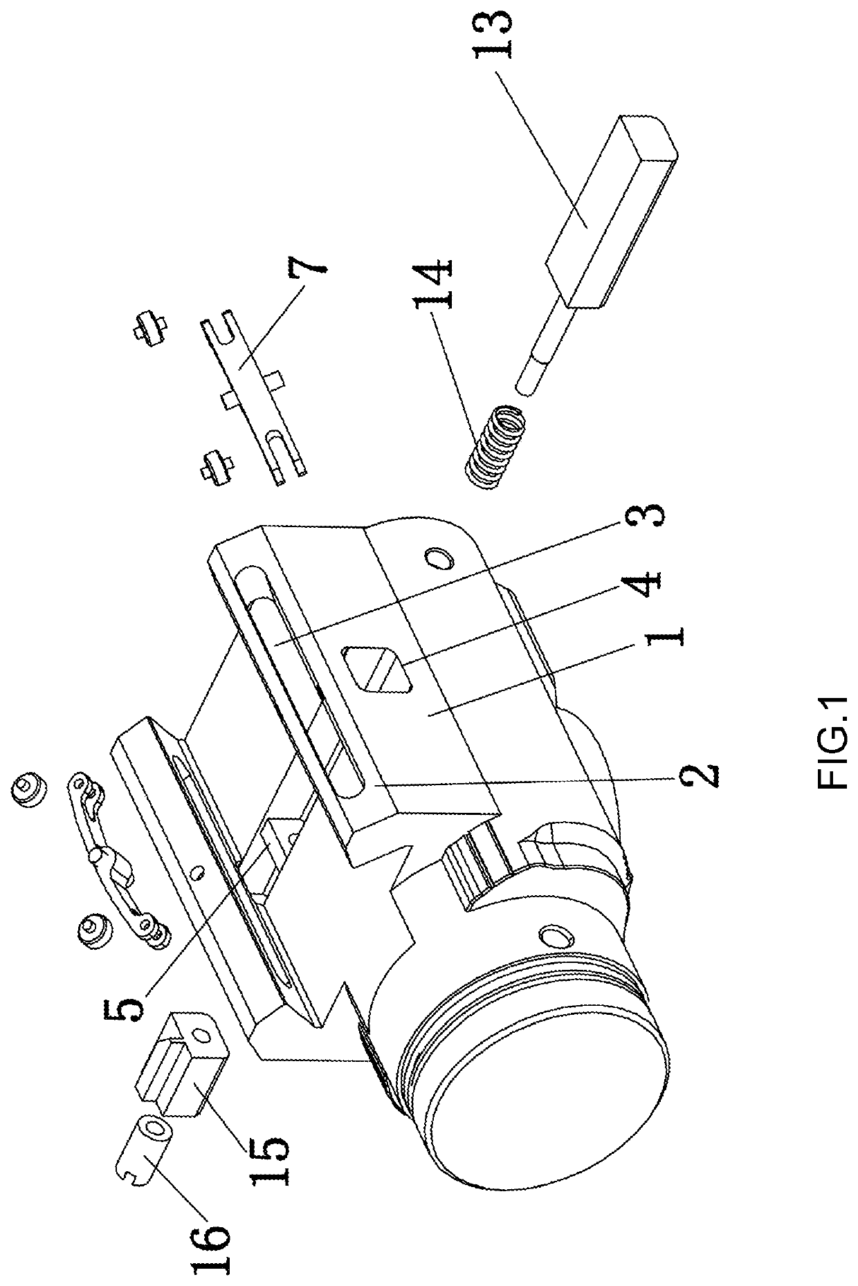
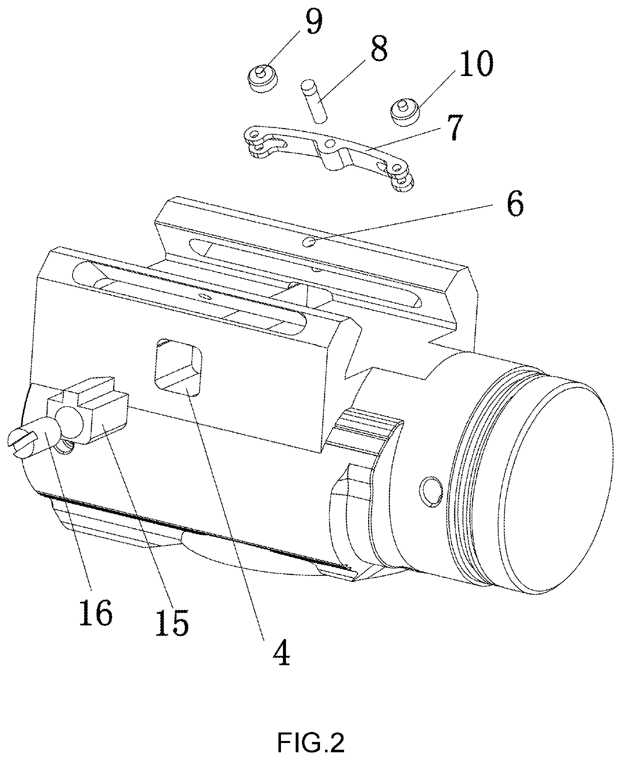
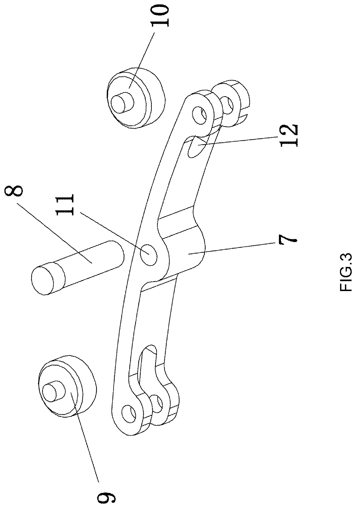
[0028]As illustrated in FIG. 1, the quick detaching device for handgun tactical light comprises a tactical light base 1, two locking members 2 correspondingly disposed on two sides of a top end of the tactical light base 1, sliding members and a pressing mechanism. A sliding slot 3 is correspondingly mounted in a middle part of each of the locking members 2 respectively. The sliding members are respectively mounted in the sliding slots 3. A through slot 4 which passes through the tactical light base 1 is provided in the tactical light base 1. The through slot 4 has a top end which is in corresponding communication with the tactical light base 1. A stopping plate 5 is provided in a middle part of the through slot 4. The pressing mechanism is mounted in the through slot 4 and corresponds to the stopping plate 5. The present invention could be mounted on common handguns. A common han...


PUM

PropertyMeasurementUnit
mass fractionaaaaaaaaaa
elasticaaaaaaaaaa

Abstract

This invention provides a quick detaching device for handgun tactical light which includes a tactical light base, two locking members correspondingly disposed on two sides of a top end of the tactical light base, sliding members and a pressing mechanism; a sliding slot is correspondingly mounted in a middle part of each of the sliding members; the sliding members are respectively mounted in the sliding slots; a through slot which passes through the tactical light base is provided in the tactical light base; a stopping plate is provided in a middle part of the through slot; the pressing mechanism is mounted in the through slot and corresponds to the stopping plate. This invention can quickly mount and detach the tactical light without the help of tools and great effort, and is convenient to use.

Description

BACKGROUND OF THE INVENTION[0001]The present invention belongs to the technical field of portable lighting apparatus and more particularly pertains to a quick detaching device for handgun tactical light.[0002]When a common tactical light is in use, it is necessary to first loosen the nut and then open the clamping mechanism before the tactical light could be detached. This kind of design is inconvenient in that the tactical light could only be detached by hand with great strength or with tools. In outdoor environment where there is no tools or when the user does not have sufficient strength, user operation is very inconvenient and the detaching process takes relatively long time. Besides, tactical lights are equipped with charging function. When the battery of the tactical light runs out and requires charging, frequency would be higher and the detaching process is troublesome. It is even more troublesome when the user wishes to use the tactical light as a torch. This results in incr...

Claims


Application Information

Patent Timeline
Patent Type & Authority Applications(United States)
IPC IPC(8): F41G11/00F41C27/00
CPCF41G11/004F41C27/00F21V21/08F21V17/12F21V17/10C08L63/00C08L2201/08C08L75/04C08K7/06C08K3/28C08K5/09C08K13/04F41G11/003
Inventor MA, QIANGZHOU, ZIYANG
Owner SHENZHEN OLIGHT E COMMERCE TECH CO LTD
Learn More