Electric torque wrench capable of sensing manual operating torque

a technology of manual operation and torque, which is applied in the direction of wrenches, power-driven tools, screwdrivers, etc., can solve the problems of inability to function properly, the accuracy of manual operation is reduced, and the rotation of such workpieces is difficult, so as to achieve the effect of precise manual operation torque value and increasing production yield ra

Active Publication Date: 2021-04-29
TECHWAY INDAL
View PDF0 Cites 3 Cited by
  • Summary
  • Abstract
  • Description
  • Claims
  • Application Information

AI Technical Summary

Benefits of technology

[0018]For the electric torque wrench capable of sensing a manual operating torque provided by the present invention, the ring gear member is connected to the driving device; therefore, the motor can be used as a power source to drive the working head to rotate, and the manual method can also be utilized to exert a torque. The deformation generated during the manual exertion of the torque is able to cause the generation of deformation on the driving device and the extension arm on the ring gear member connected to the driving device, such that the torque sensing unit installed on the extension arm can be used to measure the torque, thereby providing a precise manual operating torqu

Problems solved by technology

However, during the moment when the workpiece is about to be fastened tightly, the rotation of such workpiece becomes more difficult, and the motor is required to generate greater torque to fasten the workpiece firmly.
Nevertheless, during the fastening process, the driving force of the motor is subject to the effect of inertial force such that the torque value exerted tends to exceed the setting torque value, thereby causing a difference between the actual fastening torque value and the setting torque value.
As a result, its precision is reduced or cannot function properly.
On the other hand, if the baking process is performed on the transducer assembly (118) and the strain gauge (142) first and then assembled onto the

Method used


Image

  • Electric torque wrench capable of sensing manual operating torque
  • Electric torque wrench capable of sensing manual operating torque
  • Electric torque wrench capable of sensing manual operating torque

Examples


Embodiment Construction

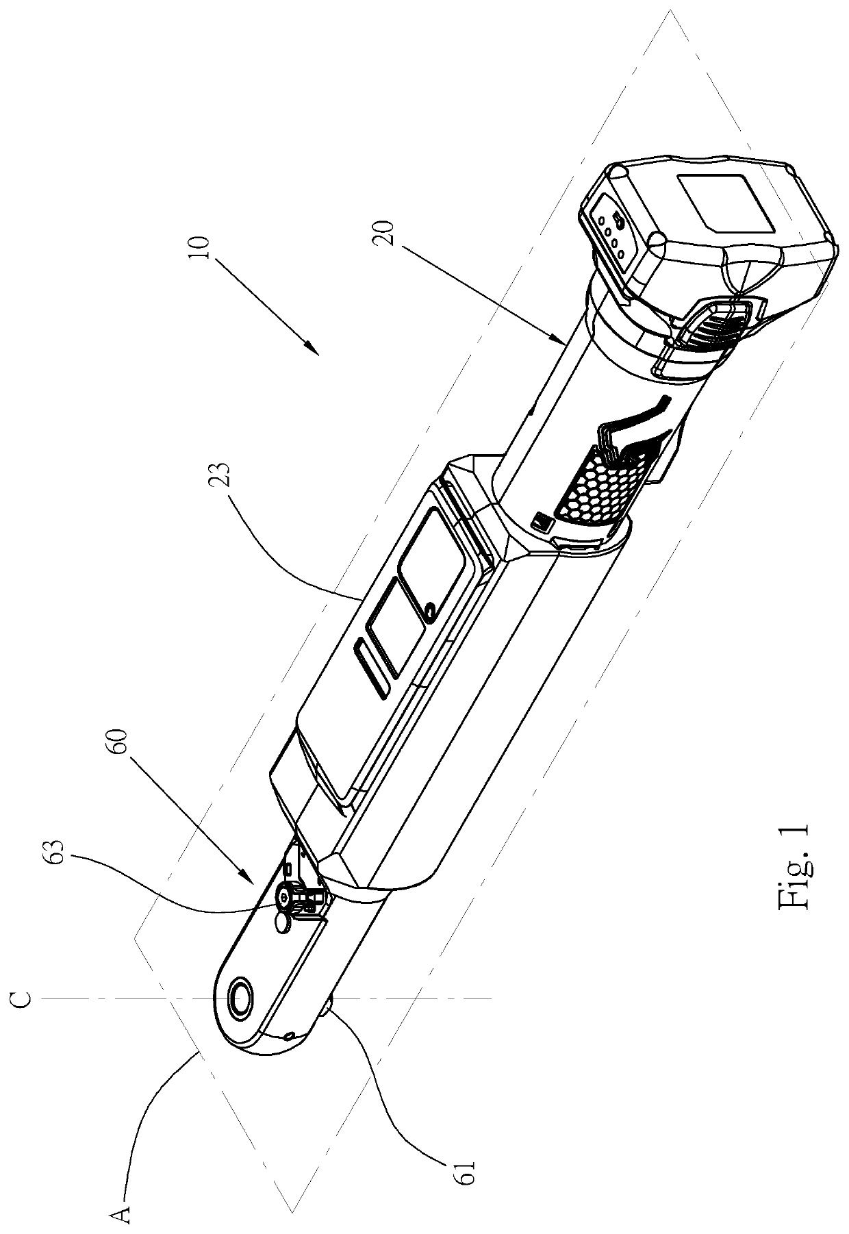
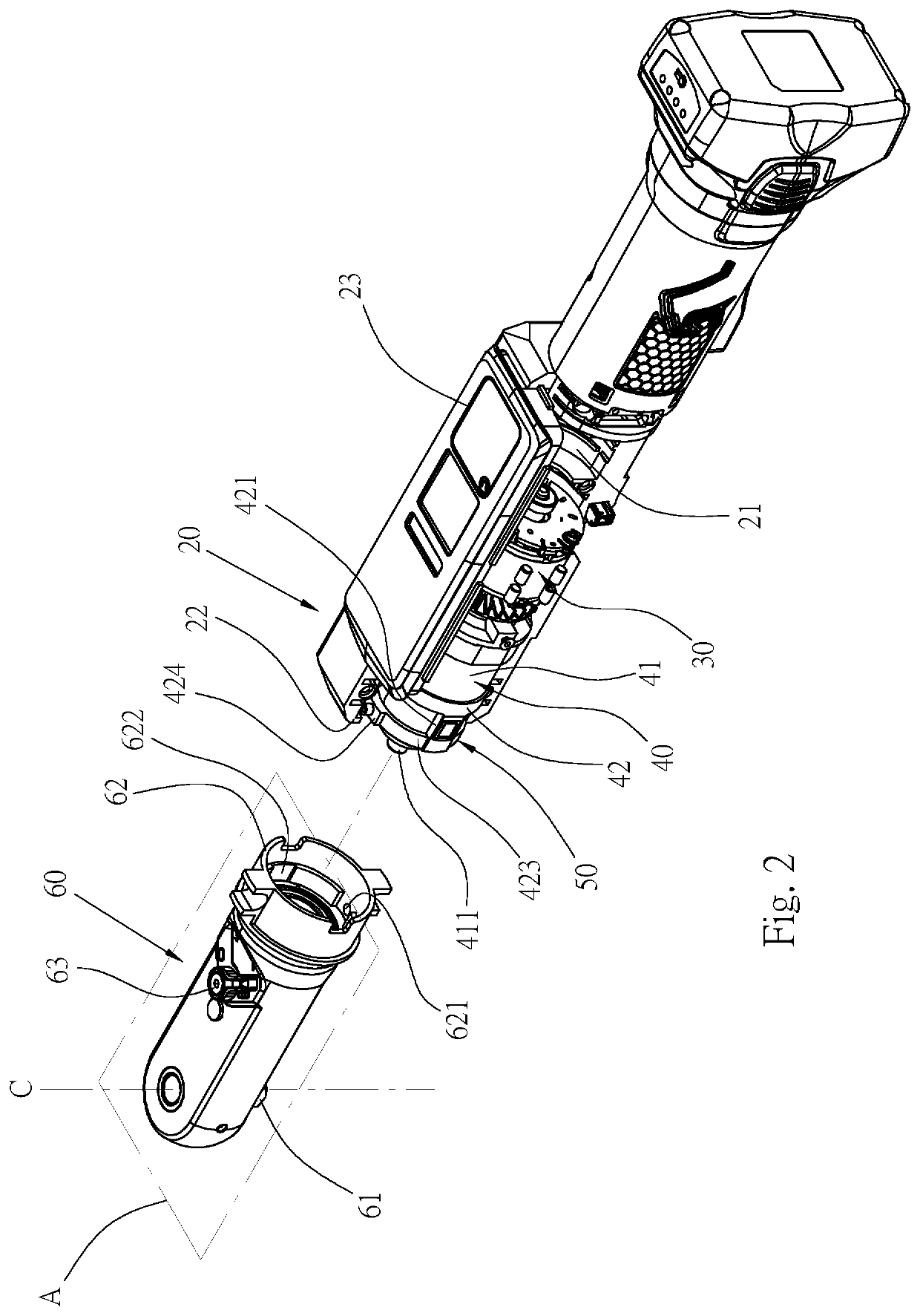
[0030]Please refer to FIG. 1 to FIG. 2, showing an electric torque wrench 10 according to a preferred embodiment of the present invention, comprising:

[0031]An outer housing 20 includes an accommodating space 21 at an internal thereof and a front end with an opening 22 formed thereon. The external of the outer housing 20 includes a human-machine interface 23, and the human-machine interface 23 can be equipped with different configuration of a microprocessor, operating buttons and a display screen etc. depending upon the needs such that an interface connected to the electric torque wrench can be provided to the user. Since this part belongs to the structure of a known electric torque wrench, details thereof are omitted hereafter.

[0032]A motor 30 includes a driving shaft 31, as shown in FIG. 4, facing toward the direction of the opening 22 of the outer housing 20. The motor 30 is arranged inside the accommodating space 21 of the outer housing 20, and it is configured to be driven by a ...


PUM


Abstract

An electric torque wrench capable of sensing a manual operating torque includes: an outer housing having an accommodating space at an internal thereof, a motor and a reduction device arranged therein; the reduction device having a reduction gear assembly with a hollow ring gear member; a front end of the ring gear member having at least one extension arm and at least one sensing plane formed thereon; a torque sensing unit arranged on the sensing plane; a driving device installed at the front end of the outer housing and having a working head arranged at the front end thereof; the extension arm of the ring gear member secured and attached onto the driving device. With the torque sensing unit installed on the extension arm, the electric torque wrench can be rotated manually with hand and is able to measure the torque value.

Description

BACKGROUND OF THE INVENTION1. Technical Field[0001]The present invention relates to an electric tool, and in particular, to an electric torque wrench capable of sensing a manual operating torque by utilizing a reduction device installed with a torque sensing unit thereon such that it is able to detect a manual driving torque.2. Description of Related Art[0002]A known electric torque tool mainly utilizes a motor as a driving source, and a torque can be generated via motor driving in order to allow a workpiece, such as a screw, to generate axial rotation, thereby achieving the effect of fastening or unfastening the workpiece. During the fastening or unfastening of the workpiece performed by a known electric torque tool, since its torque is relatively small, motor is able to rotate at high speed continuously, such that the performance time can be reduced. However, during the moment when the workpiece is about to be fastened tightly, the rotation of such workpiece becomes more difficult...

Claims


Application Information

Patent Timeline
IPC IPC(8): B25B23/147B25B13/06
CPCB25B23/147B25B23/0014B25B13/06B25B21/00B25B23/1425
Inventor HSU, CHIH-HUACHEN, WEI-MING
Owner TECHWAY INDAL
Why Eureka
Try Eureka