Laser device and tissue characterizing method

a tissue and laser technology, applied in the field of laser devices, can solve the problems of inability to react during the intervention, time-consuming and cumbersome biopsies, and processes that do not allow for reaction, so as to achieve precise local position and capture the image captured by the camera

Pending Publication Date: 2021-05-06
ADVANCED OSTEOTOMY TOOLS - AOT
View PDF0 Cites 0 Cited by
  • Summary
  • Abstract
  • Description
  • Claims
  • Application Information

AI Technical Summary

Benefits of technology

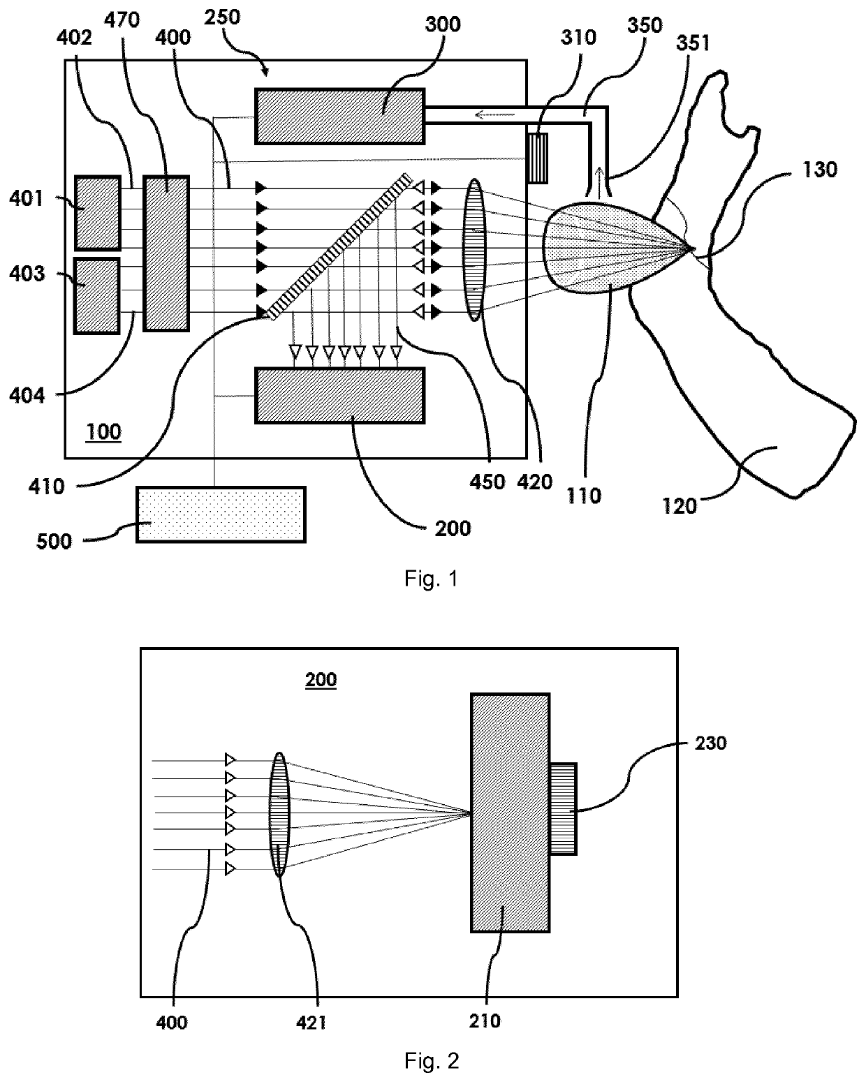
[0068]Particularly, the plume analyzing arrangement preferably is adapted to augment the image captured by the camera with information derived from the substance in the debris of the plume. Like this, the information about the substance can be associated to the image of the target tissue. For example, the type of the substance or the substance itself can be three-dimensionally displayed in the image. In particular, such display can be performed more or less runtime such that a practitioner continuously knows what kind of tissue is ablated by the laser beam. This, e.g. allows for precisely knowing when a cancer tissue is ablated and when the end of the cancerous tissue is reached.
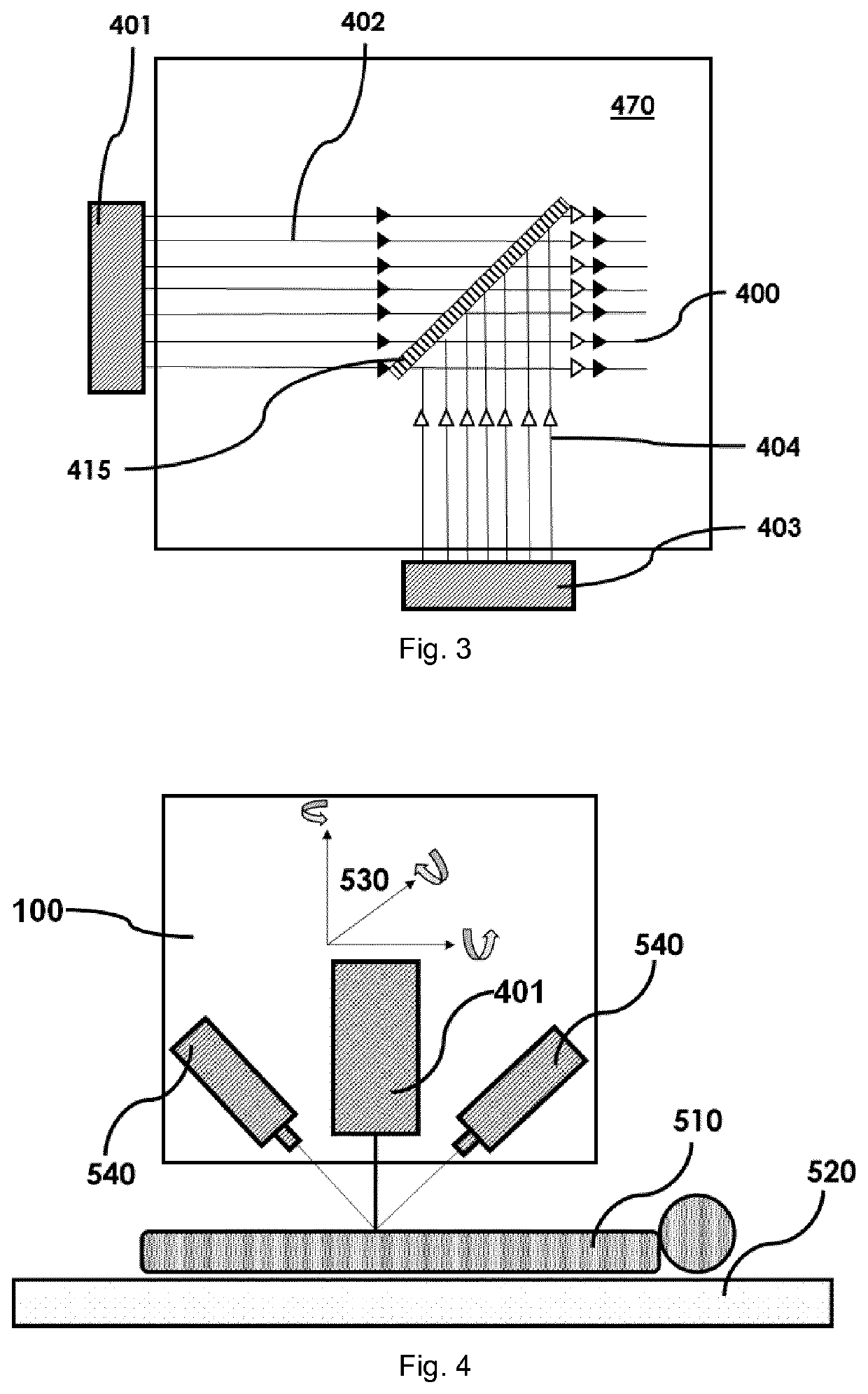
[0069]Preferably, the ablation laser source is three-dimensionally movable, particularly, relative to the target tissue. More specifically, the ablation laser source can be movable along and/or about an x-axis, a y-axis and a z-axis. For example, the x- and y-axes can be in a plane more or less parallel to a surface of the target tissue and the y-axis can be directed towards the target tissue (depth). Like this, the laser beam can be precisely directed to and positioned at any suitable location of the target tissue. This allows for the target tissue being fixed or stationary

Problems solved by technology

For example, tumour recognition and precise tumour margin detection represents a central challenge during a surgical intervention such as a tumour removal in bone.
Indeed, and despite the recent technological advances, b

Method used


Image

  • Laser device and tissue characterizing method
  • Laser device and tissue characterizing method
  • Laser device and tissue characterizing method

Examples


Embodiment Construction

[0086]In the following description certain terms are used for reasons of convenience and are not intended to limit the invention. The terms “right”, “left”, “up”, “down”, “under” and “above” refer to directions in the figures. The terminology comprises the explicitly mentioned terms as well as their derivations and terms with a similar meaning. Also, spatially relative terms, such as “beneath”, “below”, “lower”, “above”, “upper”, “proximal”, “distal”, and the like, may be used to describe one element's or feature's relationship to another element or feature as illustrated in the figures. These spatially relative terms are intended to encompass different positions and orientations of the devices in use or operation in addition to the position and orientation shown in the figures. For example, if a device in the figures is turned over, elements described as “below” or “beneath” other elements or features would then be “above” or “over” the other elements or features. Thus, the exempla...


PUM


Abstract

A laser device (100) has an ablation laser source (401) adapted to provide an ablating laser beam (402; 402i) for ablating a target tissue (120). It further comprises a plume analyzing arrangement (250) adapted to identify and/or quantify substances in the debris of the plume (110) generated by the ablating laser beam (402) ablating the target tissue (120) particularly substances being biomarkers of the ablated target tissue (120).

Description

TECHNICAL FIELD[0001]The present invention relates to a laser device according to the preamble of independent claim 1 and more particularly to a tissue characterizing method.[0002]Such laser devices comprising an ablation laser source adapted to provide an ablating laser beam for ablating a target tissue can be used in many applications such as in medical or surgical applications where a human or animal natural tissue is to cut or to ablate otherwise.BACKGROUND ART[0003]For cutting and drilling human or animal hard or soft tissue such as bones, cartilages or the like various different tools such as saws, chisels or drills are commonly used since a long time. In recent years, also cutting and drilling with laser beam is becoming more and more popular. For example, in some computer assisted surgery it is known to use laser beams as cutting instruments. More particularly, e.g., in WO 2011 / 035792 A1 a computer assisted and robot guided laser osteotomic medical device is described which ...

Claims


Application Information

Patent Timeline
IPC IPC(8): A61B18/20
CPCA61B18/203A61B2018/00642A61B2018/00702A61B18/20A61B5/0075A61B2018/00577A61B2018/00565A61B2018/2253A61B2018/20361A61B2018/20359A61B2018/2283A61B2018/00982A61B2017/00061A61B2218/008
Inventor BRUNO, ALFREDO E.BÖRNSEN, KLAUS OLAF
Owner ADVANCED OSTEOTOMY TOOLS - AOT
Why Eureka
Try Eureka