Acoustic treatment panel for a turbojet engine

Active Publication Date: 2021-05-06
SN DETUDE & DE CONSTR DE MOTEURS DAVIATION S N E C M A
0 Cites 0 Cited by

AI-Extracted Technical Summary

Problems solved by technology

This results in a lowering of the frequencies of the acoustic radiation.
This makes the panels incompatible with the constraints of mass and space requirement associated with the new UHBR (Ultra High Bypass Ratio) type architectures.
This restriction on the attenuation frequency bandwidth is very penalizing, because the variati...

Method used

[0068]In order to increase the length of the channels 20 and thereby decrease the frequencies of the sound waves which can be treated by the acoustic treatment panel 10, the channels 20 extend into the input layer 16 so as to have a length greater than the thickness e of the input layer 16, the thickness e of the input layer corresponding to the distance separating the first face 161 from the second face 162 of the input layer measured in a direction orthogonal to the planes in which the two faces 161 and 162 of the input layer 16 extend.
[0069]The channels 20 can have simple or, preferably, complex shapes. The co...

Benefits of technology

[0015]The invention aims at providing an acoustic treatment panel making it possible to overcome the drawbacks mentioned above and including in particular resonators capable of attenuating the radiation associated with the noise of the low-frequency lines eff...

Abstract

An acoustic treatment panel intended to be disposed on at least one wall of a turbojet engine in contact with a fluid flow, the panel including a first acoustically reflective plate, a second plate and a plurality of cavities mounted between the first plate and the second plate and including a plurality of cells. The second plate is a one-piece plate through which a plurality of channels pass, each opening out on the one hand onto a first orifice formed on a first face of the second plate and on the other hand onto a second orifice formed on a second face of the second plate, the length of each channel extending between its first orifice and its second orifice being greater than the thickness of the second plate.

Application Domain

Engine manufactureEfficient propulsion technologies +3

Technology Topic

PhysicsAcoustic reflection +2

Image

  • Acoustic treatment panel for a turbojet engine
  • Acoustic treatment panel for a turbojet engine
  • Acoustic treatment panel for a turbojet engine

Examples

  • Experimental program(1)

Example

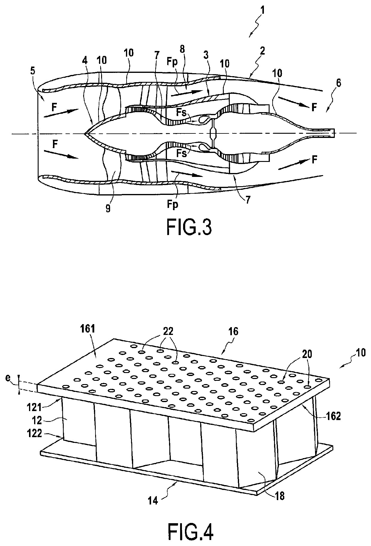
[0050]FIG. 3 represents a sectional view of a turbojet engine 1 according to one embodiment of the invention, in a longitudinal plane of the turbojet engine 1.
[0051]The turbojet engine 1 comprises a nacelle 2, an intermediate casing 3 and an internal casing 4. The nacelle 2 and the two casings 3 and 4 are coaxial. The nacelle 2 defines at a first end an inlet channel 5 for a fluid flow and at a second end, opposite the first end, an exhaust channel 6 for a fluid flow. The nacelle 2 and the intermediate casing 3 delimit therebetween a primary fluid flowpath 7. The intermediate card 3 and the internal casing 4 delimit therebetween a secondary fluid flowpath 8. The primary flowpath 7 and the secondary flowpath 8 are disposed along an axial direction of the turbojet engine between the inlet channel 5 and the exhaust channel 6.
[0052]The turbojet engine 1 further comprises a fan 9 configured to deliver an air stream F as a fluid flow, the air stream F being divided at the outlet of the fan into a primary stream FP circulating in the primary flowpath 7 and into a secondary stream FS circulating in the secondary flowpath 8.
[0053]The turbojet engine 1 further comprises at least one acoustic treatment panel 10 configured to attenuate the acoustic waves emitted by the turbojet engine before these waves escape, radially, outside the nacelle 2 of the turbojet engine 1.
[0054]Each acoustic treatment panel 10 is configured to attenuate acoustic waves whose frequency belongs to a predetermined range of frequencies. In the embodiment illustrated in FIG. 3, the acoustic treatment panels 10 are integrated to the nacelle 2, to the intermediate casing 3 and to the internal casing 4. On the internal casing 4, the acoustic treatment panels 10 are integrated, on the one hand, onto the portion upstream the intermediate casing 3 along the axial direction and in particular onto the portion carrying the fan 9 and, on the other hand, onto a portion downstream of the intermediate casing 3.
[0055]FIG. 4 represents a partial perspective view of an acoustic treatment panel 10 according to one embodiment of the invention.
[0056]Referring to FIG. 4, the acoustic treatment panel 10 includes a core 12, a reflective layer 14 and an input layer 16.
[0057]The core 12 has a honeycomb structure. More specifically, the core 12 includes a plurality of cells 18 arranged in a known honeycomb structure.
[0058]Each cell 18 opens out onto a first face 121 of the core 12 and onto a second face 122 of the core 18 located opposite the first face 121.
[0059]The first face 121 of the core 12 is intended to be oriented towards the primary 7 or secondary 8 air flowpath depending on the location of the acoustic treatment panel 10. The second face 122 of the core 12 is intended to be facing away the air flowpath.
[0060]Preferably, the core 12 is such that the distance between the first face 121 and the second face 122 is on the order of a quarter of the wavelength corresponding to a predetermined working frequency.
[0061]The working frequency is a frequency for which a maximum acoustic attenuation is desired. The working frequency belongs to the predetermined range of frequencies.
[0062]According to the embodiment, the core 12 can be made of metal or of a composite material such as a composite material formed of carbon fibers embedded in a cured resin matrix.
[0063]The reflective layer 14 is adapted to reflect acoustic waves having a frequency belonging to the predetermined range of frequencies.
[0064]The reflective layer 14 extends opposite the second face 122 of the core 12, being in contact with the second face 122. More specifically, the reflective layer 14 is secured to the second face 122 of the core 12, for example bonded to the second face 122 of the core 12.
[0065]According to the embodiment, the reflective layer 14 can be made of metal or of a composite material, such as a composite material formed of carbon fibers embedded in a cured resin matrix.
[0066]The input layer 16 extends opposite the first face 121 of the core 12, being in contact with the first face 121. More specifically, the input layer 16 is secured to the first face 121 of the core 12, for example bonded to the first face 121 of the core 12.
[0067]The input layer 16 is a one-piece plate formed by additive manufacturing. It comprises a plurality of channels 20 passing through the input layer 16 from a first opening 22 made on the first face 161 of the input layer 16 up to a second opening 24 made on the second face 162 of the input layer 16. The second opening 24 of each channel 20 opens out onto a cell 18 of the core 12, several channels 20 being able to open out onto the same cell 18.
[0068]In order to increase the length of the channels 20 and thereby decrease the frequencies of the sound waves which can be treated by the acoustic treatment panel 10, the channels 20 extend into the input layer 16 so as to have a length greater than the thickness e of the input layer 16, the thickness e of the input layer corresponding to the distance separating the first face 161 from the second face 162 of the input layer measured in a direction orthogonal to the planes in which the two faces 161 and 162 of the input layer 16 extend.
[0069]The channels 20 can have simple or, preferably, complex shapes. The complex three-dimensional shapes allow optimizing the dimensioning of the necks by maximizing the space they occupy in the volume of the input layer 16.
[0070]The channels, simple or complex, have preferably lengths greater than 1.5 times the thickness e of the input layer 16.
[0071]FIGS. 5A to 5F schematically represent exemplary embodiments of the channels of the acoustic treatment panel 10.
[0072]FIG. 5A presents an input layer 16 with channels 20 having a helical shape oriented along the thickness e of the input layer 16. The path of the channel 20 corresponds to a helicoid that winds about an axis oriented along the thickness e of the input layer 16.
[0073]FIG. 5B presents an input layer 16 with channels 20 having a helical shape oriented perpendicular to the thickness e of the input layer 16. The path of the channel 20 corresponds to a helicoid that winds about an axis oriented perpendicular to the thickness e of the input layer 16.
[0074]FIG. 5C presents an input layer 16 with serpentine-shaped channels 20 oriented along the thickness e of the input layer 16. A serpentine has a plurality of layers and extends generally in the same plane. The path of the channel 20 corresponds to a serpentine whose greatest length is oriented along the thickness e of the input layer 16.
[0075]FIG. 5D presents an input layer 16 with channels 20 having the shape of a serpentine oriented perpendicular to the thickness e of the input layer 16. The path of the channel 20 corresponds to a serpentine whose greatest length is oriented perpendicular to the thickness e of the input layer 16.
[0076]FIG. 5E presents an input layer 16 with channels 20 having a double-helicoid configuration. Two adjacent channels wind in a double helicoid whose axis is oriented along the thickness e of the input layer 16. The path of each channel 20 corresponds to a helicoid that winds about an axis oriented along the thickness e of the input layer 16. This type of configuration, in combination of several channels, can have the advantage of minimizing the curvatures of the channel, and therefore the acoustic resistivity thereof.
[0077]FIG. 5F presents an input layer 16 with two adjacent channels winding in a double helicoid whose axis is oriented perpendicular to the thickness e of the input layer 16. The path of each channel 20 corresponds to a helicoid that winds about an axis oriented perpendicular to the thickness e of the input layer 16.
[0078]It is also possible to envisage a multi-helicoidal configuration with several neighboring channels winding along a helicoid of common axis, oriented along the thickness e of the input layer or perpendicular thereto.
[0079]Any other overlay of regular patterns can also be envisaged.
[0080]Technologies such as three-dimensional printing on a powder bed or by depositing material can be envisaged to design the input layer. It is enough to be able to achieve a certain accuracy, on the order of 0.1 mm minimum.
[0081]This optimization allows tuning the treatment to lower frequencies without significantly increasing the total height of the treatment and by retaining the conventional processes of developing the honeycomb treatments.
[0082]Preferably, the frequency tuning of the acoustic treatment panel 10 satisfies, as a first approximation, the following equation:
F = C 2 ⁢ π ⁢ S Vl ′
[0083]With F the tuning frequency in Hertz, C the velocity of the sound in meters per second, S the section of the channel in square meters, V the volume of the resonator in meters, I′ the corrected channel length, where
l′=l+δ
[0084]with l the geometric length of the channel, and δ the correction of the channel where
δ=1.7r(1−0.7√{square root over (σ)})
[0085]for juxtaposed resonators, with r the radius of an orifice, and σ the perforation rate.
[0086]Preferably, the length of the channel is greater than its diameter, at least 1.5 times greater, to guarantee the desired properties to the air column it contains. The distance between the second opening 24 of the channels 20, in other words, the second face 162 of the input layer, and the reflective layer 14 is greater than a quarter of the height of the channel. The section of the channel is comprised between 0.2 mm2 and 7 mm2. A single cavity can contain several necks. The spacing between each neck should be greater than a neck diameter.
[0087]As illustrated in FIG. 6 which schematically presents a sectional view of the acoustic treatment panel of FIG. 4, each cavity 18 of the core 12 opens out onto a plurality of channels 20 of the input layer 16. In other words, several channels 20 of the input layer 16 open out onto the same cavity 18 of the core 12.
[0088]Furthermore, as illustrated in FIG. 7 which schematically presents a zoom of a portion of a channel of the acoustic treatment panel of FIG. 4, each channel 20 preferably has a first end portion 202 extending from the first opening 22 and a second end portion 204 extending from the second opening 24. Each of the first and second end portions 202 and 204 extends within the thickness of the input layer 16, from respectively the first and second openings 22 and 24, in a direction, respectively X1 and X2, forming an angle θ of at most 15° with a straight line, respectively Z1 and Z2, orthogonal to the plane in which the input layer 16 extends.
[0089]In other words, each of the first and second end portions 202 and 204 extends in a direction forming an angle comprised between 75° and 90° with the face of the input layer 16 onto which it opens out, namely respectively the first face 161 and the second face 162. This angle promotes permeability of the input layer 16 to acoustic waves, in particular at the inlet in the panel 10, and improves the operation of the cavities 18 at the outlet of the input layer 16.
[0090]The invention thus provides an acoustic treatment panel making it possible to overcome the drawbacks mentioned above and including in particular resonators capable of attenuating the radiation associated with the noise of the low-frequency lines effectively on a turbomachine speed for a greatly reduced space requirement compared to a conventional honeycomb-type treatment and while retaining the conventional processes of developing the honeycomb treatments.

PUM

no PUM

Description & Claims & Application Information

We can also present the details of the Description, Claims and Application information to help users get a comprehensive understanding of the technical details of the patent, such as background art, summary of invention, brief description of drawings, description of embodiments, and other original content. On the other hand, users can also determine the specific scope of protection of the technology through the list of claims; as well as understand the changes in the life cycle of the technology with the presentation of the patent timeline. Login to view more.

Similar technology patents

Air treatment system, and related vehicles and methods

PendingUS20220176289A1reduced space requirement
Owner:AGCO INT GMBH

Compact Drain Assembly for Sinks and the Like

InactiveUS20090044331A1reduced space requirementeliminate drawback
Owner:ELLECI

Multi-zone heat sink for printed circuit boards

ActiveUS11310903B2reduced space requirement
Owner:DSPACE DIGITAL SIGNAL PROCESSING & CONTROL ENG

Variable firework battery

ActiveUS10323915B2reduced space requirementsimple and cost-effective
Owner:THIEME RINGO

Classification and recommendation of technical efficacy words

  • reduced space requirement

Airport map system with compact feature data storage

InactiveUS6862519B2reduced space requirementeasily access
Owner:SMITHS AEROSPACE INC

Elevator device for a multi-sky-lobby system

ActiveUS20050077115A1reduced space requirementreduce space occupy
Owner:OTIS ELEVATOR CO

Input element for a telephone

InactiveUS7146005B1reduced space requirementeasily confuse
Owner:SIEMENS AG

Compressing index files in information retrieval

ActiveUS7028045B2reduced space requirement
Owner:TWITTER INC
Why Eureka
Try Eureka