Article for producing ultra-fine powders and method of manufacture thereof

a technology of ultra-fine powders and powders, which is applied in the direction of silicon, evaporation by spraying, cell components, etc., can solve the problems of troublesome repair of worn parts, difficult to maintain a relatively uniform degree of atomization, and high cos

Active Publication Date: 2021-05-13
GM GLOBAL TECH OPERATIONS LLC
View PDF0 Cites 12 Cited by
  • Summary
  • Abstract
  • Description
  • Claims
  • Application Information

AI Technical Summary

Benefits of technology

[0003]Conventional atomizing devices of the type described above are subject to certain disadvantages. While the atomization obtained is suitable for many commercial operations, it is difficult to maintain a relatively uniform degree of atomization, particularly for different types of feed material. Uniform atomization is desirable because it greatly facilitates proper operation of the spray drier. It avoids objectionable discharge of oversized particles against the side walls of the drier, it facilitates operation of the drier at a desired high capacity, and it tends to produce a final product having uniform moisture content. Another disadvantage is that the impact elements are subject to wear. Any attempt to repair the worn parts is troublesome and expensive, and generally the principal parts of the head must be discarded and replaced. The cost of repairing or replacing such worn parts adds considerably to the expense of spray drying operations.
[0012]In yet another exemplary embodiment, the convex surface of the first inclined rotating surface comprises a portion that is textured with grooves and patterns for facilitating comminution of a molten material that contacts it.
[0014]In yet another exemplary embodiment, a concave surface of the second inclined rotating surface comprises a portion that is textured with grooves and patterns for facilitating comminution of a molten material that contacts it.

Problems solved by technology

While the atomization obtained is suitable for many commercial operations, it is difficult to maintain a relatively uniform degree of atomization, particularly for different types of feed material.
Another disadvantage is that the impact elements are subject to wear.
Any attempt to repair the worn parts is troublesome and expensive, and generally the principal parts of the head must be discarded and replaced.
The cost of repairing or replacing such worn parts adds considerably to the expense of spray drying operations.

Method used


Image

  • Article for producing ultra-fine powders and method of manufacture thereof
  • Article for producing ultra-fine powders and method of manufacture thereof
  • Article for producing ultra-fine powders and method of manufacture thereof

Examples


Embodiment Construction

[0031]The following description is merely exemplary in nature and is not intended to limit the present disclosure, its application or uses. It should be understood that throughout the drawings, corresponding reference numerals indicate like or corresponding parts and features.

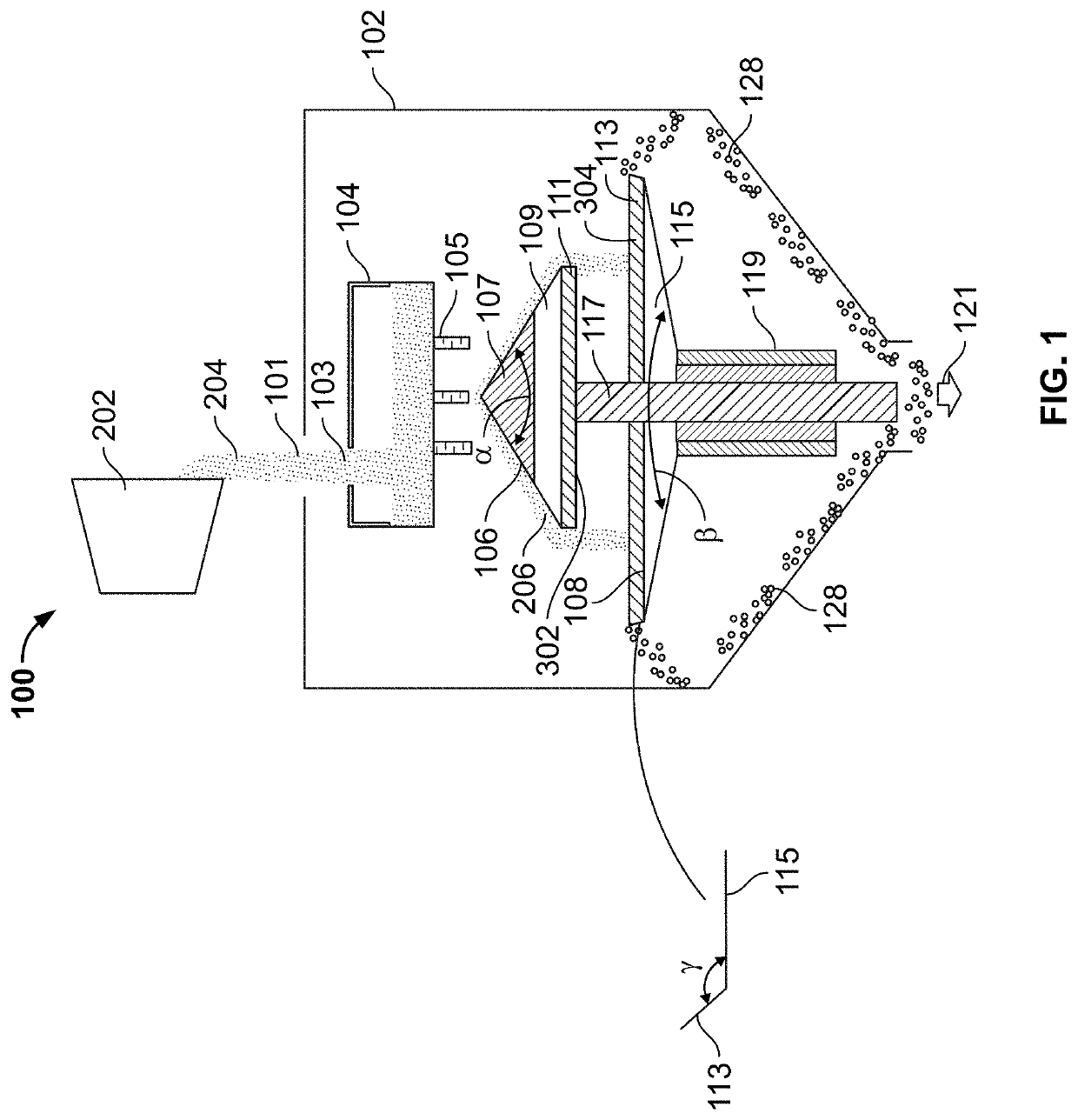
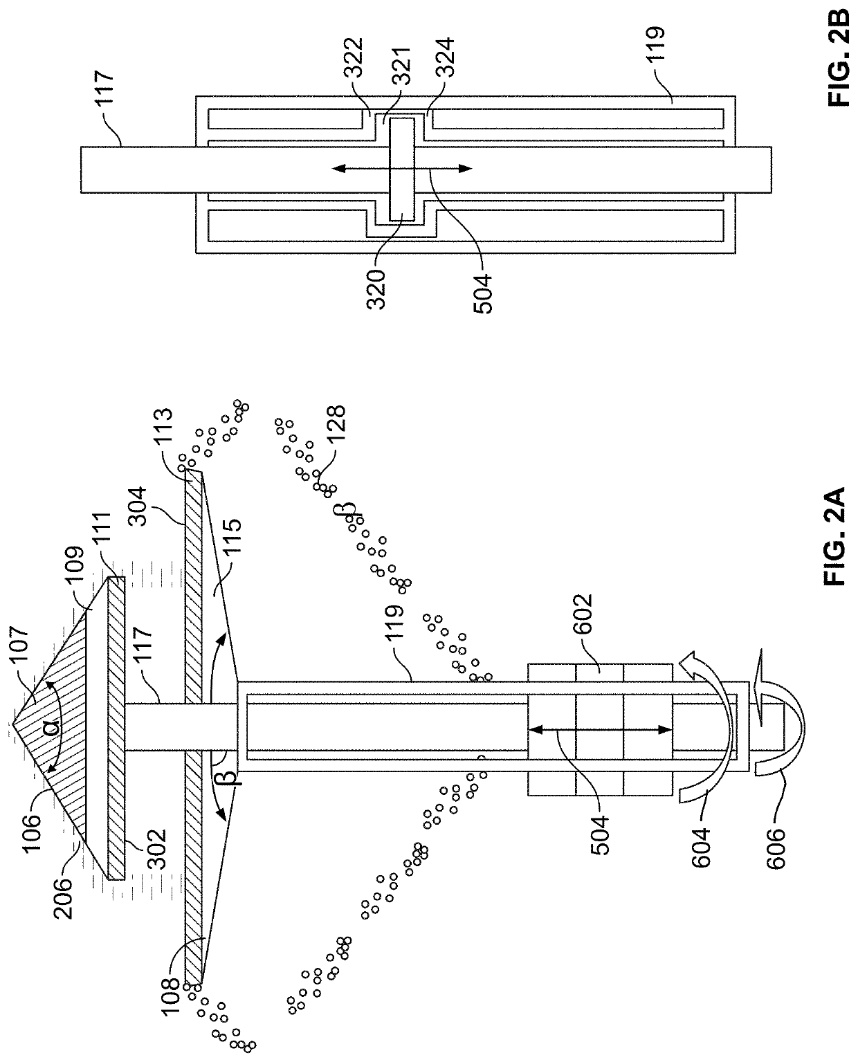
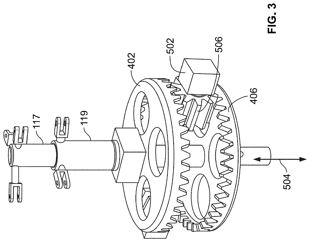
[0032]In accordance with an exemplary embodiment, disclosed herein is a multistage centrifugal atomizer whose design facilitates the production of particles that have a smaller average particle size (hereinafter ultrafine particles) with a smaller particle size distribution than other commercially available centrifugal atomizers. The multistage centrifugal atomizer increases the flow rate of molten material into the centrifuge and therefore also increases the production rate of the ultrafine particles when compared with other commercially available centrifugal atomizers. The multistage coaxial centrifugal atomizer is advantageous in that it produces ultrafine particles (with a targeted D50 of less than 20 micro...


PUM

PropertyMeasurementUnit
angleaaaaaaaaaa
D50 diameteraaaaaaaaaa
diameteraaaaaaaaaa

Abstract

A multistage centrifugal atomizer comprises an outer shell that contains an inlet port and an outlet port and that encloses a tundish, a first inclined rotating surface and a second inclined rotating surface. The first inclined rotating surface is opposedly disposed to the second inclined rotating surface. The inlet is used to introduce a molten material into the multistage atomizer and the outlet is used to remove ultrafine particles having a D50 of less than 20 micrometers.

Description

INTRODUCTION[0001]This disclosure relates to an article for producing ultra-fine powders and methods for manufacturing the article as well as the fine-powders. More particularly, this disclosure relates to a centrifugal atomizer that can be used to produce fine-powders having a very narrow polydispersity index (variation in particle sizes).[0002]Centrifugal atomizers, such as those used with spray driers, employ an atomizer head which is rotated at a relatively high speed, and to which the feed material (which is to be atomized) is supplied. The head is provided with impact elements whereby the feed material is broken up into small droplets or fragments, which are discharged outwardly for suspension in a drying gas. One particular type of atomizer head that has been widely used, employs spaced upper and lower plates which are secured to a vertical shaft, and which are connected by circumferentially spaced atomizing bars. The feed material is delivered into a space in the central por...

Claims


Application Information

Patent Timeline
Patent Type & Authority Applications(United States)
IPC IPC(8): B22F9/08B22F9/10B01J2/02C01B33/02H01M4/38
CPCB22F9/082B22F9/10B01J2/02C01P2006/40H01M4/386B22F2304/10C01P2004/61C01B33/02B01D1/18B01D1/20B01D1/30B22F9/06B22F2009/0896B22F2009/0888Y02E60/10
Inventor LIU, ZHONGYIHU, BINHUANG, XIAOSONGCAI, WAYNE
Owner GM GLOBAL TECH OPERATIONS LLC
Why Eureka
Try Eureka