
Reciprocating impact bevel tooth discharging shovel of reciprocating impact mining machine

Pending Publication Date: 2021-05-13
LIU SUHUA
View PDF0 Cites 2 Cited by
  • Summary
  • Abstract
  • Description
  • Claims
  • Application Information

AI Technical Summary

Benefits of technology

The present invention is related to a reciprocating impact bevel tooth discharging shovel for a reciprocating impact mining machine. The technical effects of this invention include reducing the height of the discharging surface of the shovel, improving impact efficiency, reducing energy consumption, and preventing fracture of the lateral discharging tooth wing plate. Additionally, the invention includes a mechanism to prevent rotation of the main impact teeth and improving the impact efficiency of the shovel.

Problems solved by technology

It often occurs that a reciprocating impact head presses against the material wall and cannot perform reciprocating impact because the impact head has a large diameter and large resistance.
It frequently occurs that a reciprocating impact counterforce of more than dozens of tons causes damage of a motor for driving reciprocating impact because of overload.
Resistance increases gradually, so that the impact head presses against the material wall and that discharging and falling of materials cannot be performed.
As a result, the reciprocating impact mining machine is of high energy consumption and time-consuming, and has low efficiency and a high failure rate, or even cannot work normally and cannot meet a desired production target.

Method used


Image

  • Reciprocating impact bevel tooth discharging shovel of reciprocating impact mining machine
  • Reciprocating impact bevel tooth discharging shovel of reciprocating impact mining machine
  • Reciprocating impact bevel tooth discharging shovel of reciprocating impact mining machine

Examples


embodiment 1

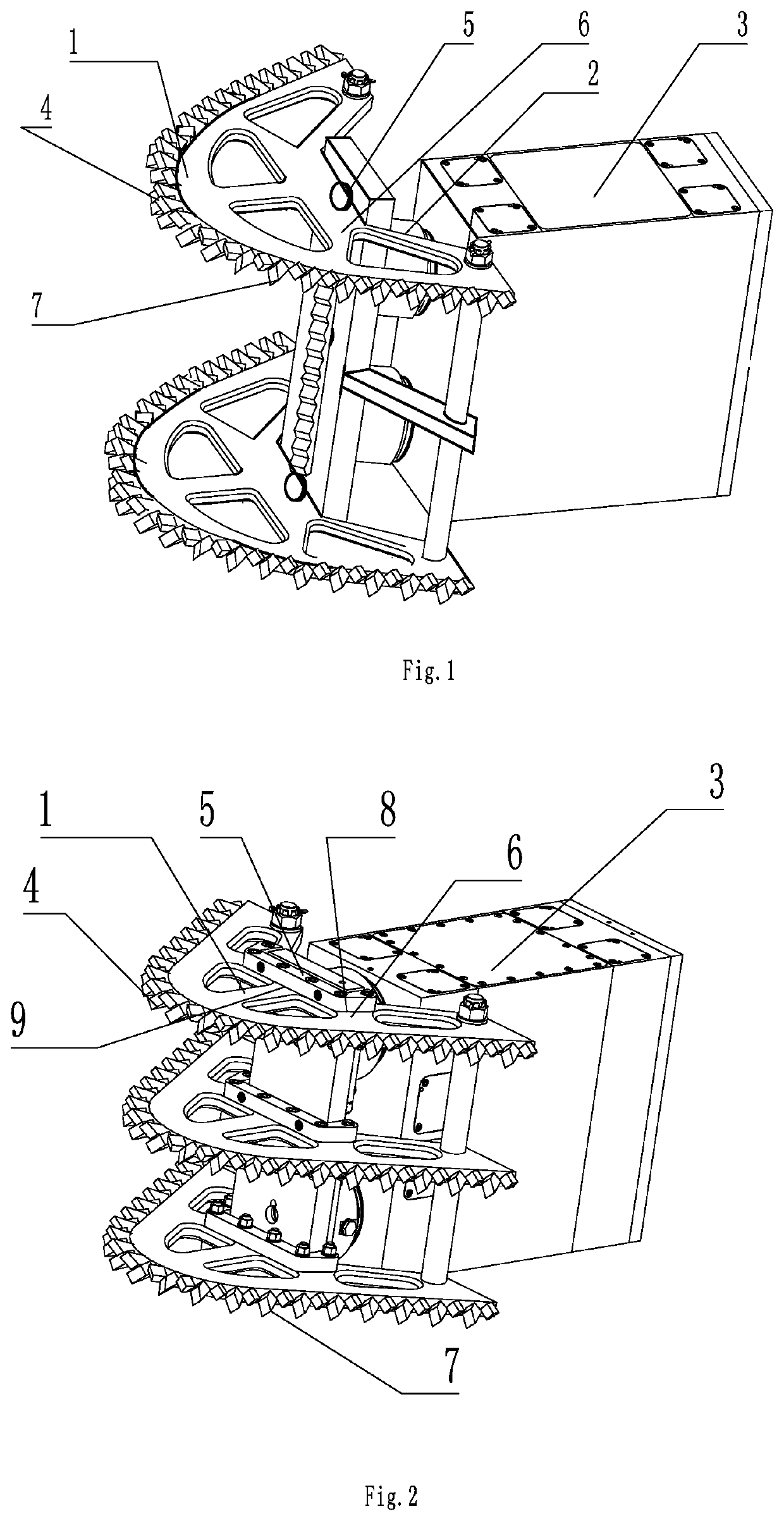
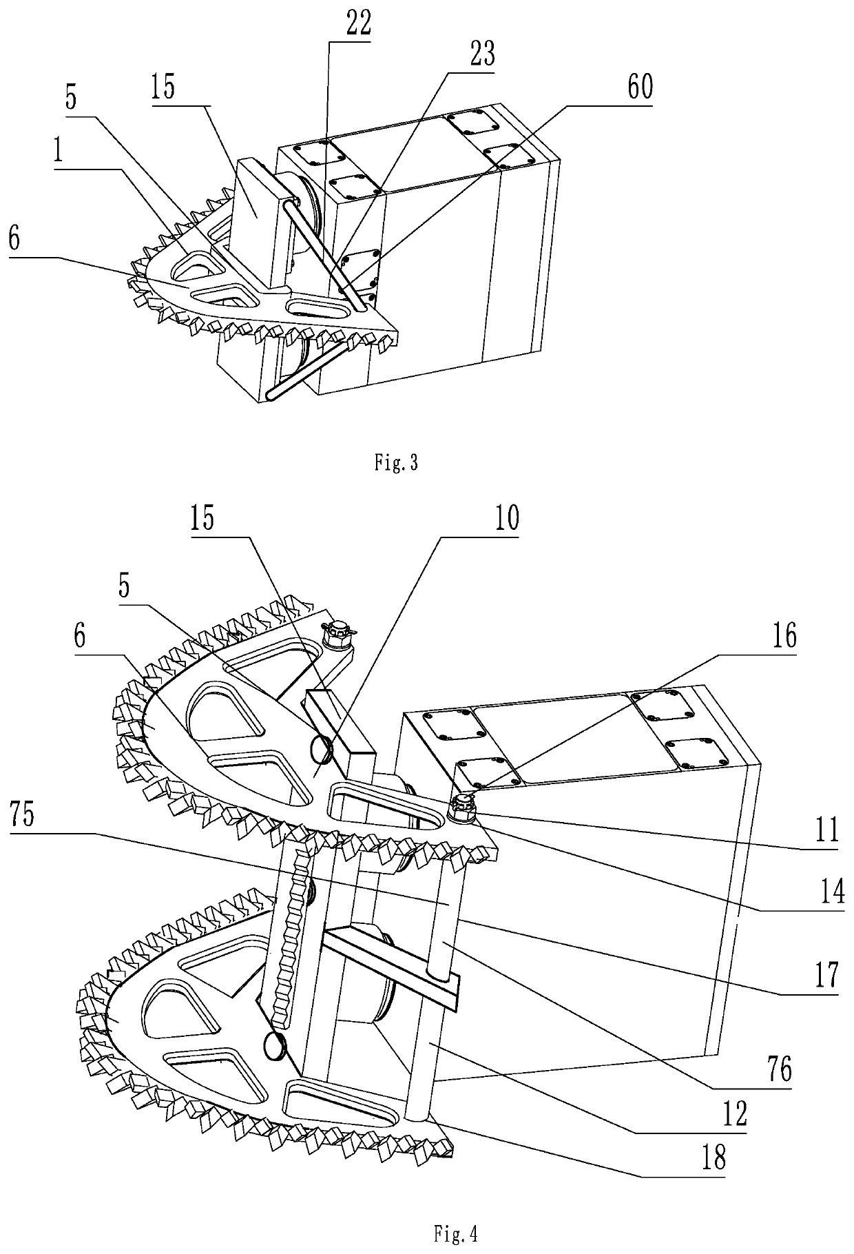
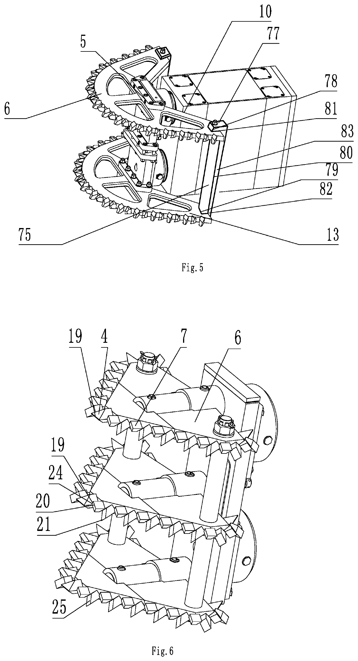
[0070]As shown in FIG. 1, a reciprocating impact bevel tooth discharging shovel of a reciprocating impact mining machine includes a reciprocating impact box and a reciprocating impact bevel tooth discharging shovel 1. The reciprocating impact box includes a reciprocating impact box body 3, a reciprocating impact power element, and a reciprocating impact guide element 2. The reciprocating impact power element is provided in the reciprocating impact box body 3, and is supported by the reciprocating impact box body 3 to drive the reciprocating impact guide element 2. One end of the reciprocating impact guide element 2 extends out of the reciprocating impact box body 3. The reciprocating impact bevel tooth discharging shovel 1 includes a main tooth seat 5, main impact teeth 4, a lateral discharging tooth wing plate 6, and lateral discharging bevel teeth 7. The main tooth seat 5 is provided at an end portion of the reciprocating impact guide element 2 extending out of the reciprocating i...

embodiment 2

[0075]FIG. 2 shows a reciprocating impact bevel tooth discharging shovel of a reciprocating impact mining machine. When the main tooth seat 5 and the main impact teeth 4 are separately connected, a lateral wing plate anti-rotation surface 8 is provided at the upper part of the lateral discharging tooth wing plate 6 extending beyond the top of the main tooth seat 5. The main impact teeth 4 are provided on the main tooth seat 5, and a side wing plate anti-rotation engaging surface 9 attaches with the side wing plate anti-rotation surface 8 so as to prevent rotation of the main impact teeth 4. The main impact teeth 4 and the main tooth seat 5 are engaged via a conical surface. A retaining element only prevents disengagement of the main impact teeth 4 from the main tooth seat 5 because the side wing plate anti-rotation surface 8 is free from rotation shearing. The side wing plate anti-rotation surface 8 has a righting effect to the main impact teeth 4.

[0076]It may also be disposed that ...

embodiment 3

[0078]As shown in FIG. 3, the reciprocating impact bevel tooth discharging shovel 1 further includes a reciprocating impact shovel plate 15. When one main tooth seat 5 is provided, a lateral discharging tooth wing plate rotation stopping element 22 is provided on the lateral discharging tooth wing plate 6. When the lateral discharging tooth wing plate rotation stopping element 22 and the lateral discharging tooth wing plate 6 are connected separately, one end of the lateral discharging tooth wing plate rotation stopping element 22 is connected with the lateral discharging tooth wing plate 6, and the other end thereof is connected with the reciprocating impact shovel plate 15. The lateral discharging tooth wing plate rotation stopping element 22 and the lateral discharging tooth wing plate 6 are connected via a rod-shaped perforation sleeve 23. The lateral discharging tooth wing plate rotation stopping element 22 includes a rod-shaped perforation sleeve wing plate rotation stopping e...


PUM


Abstract

Disclosed is a reciprocating impact bevel tooth discharging shovel of a reciprocating impact mining machine, which includes a reciprocating impact box and a reciprocating impact bevel tooth discharging shovel (1). The reciprocating impact box includes a reciprocating impact box body (3), a reciprocating impact power element, and a reciprocating impact guide element (2). One end or both ends of the reciprocating impact guide element (2) extend out of the reciprocating impact box body (3). The reciprocating impact bevel tooth discharging shovel (1) includes a main tooth seat (5), main impact teeth (4), a lateral discharging tooth wing plate (6), and lateral discharging bevel teeth (7). The impacted materials are discharged from a gap which is formed by the lateral discharging bevel teeth (7) towering over the lateral discharging tooth wing plate (6), which reduces resistance of the materials to the reciprocating impact bevel tooth discharging shovel (1).

Description

FIELD OF THE INVENTION[0001]The present disclosure relates to the field of mining machinery, and in particular, to a reciprocating impact bevel tooth discharging shovel of a reciprocating impact mining machine.BACKGROUND OF THE INVENTION[0002]When an existing reciprocating impact mining machine is used to impact a rock wall, a coal wall, copper ore, iron ore, and so on, since an impact head has a small diameter at the front end and a large diameter at a rear end, without a discharging structure, materials impacted by the front end of the impact head is pressed on a material wall by the rear end of the impact head, consequently a harder material surface is formed. It often occurs that a reciprocating impact head presses against the material wall and cannot perform reciprocating impact because the impact head has a large diameter and large resistance. It frequently occurs that a reciprocating impact counterforce of more than dozens of tons causes damage of a motor for driving reciproc...

Claims


Application Information

Patent Timeline
IPC IPC(8): E21C27/28E21C35/20
CPCE21C27/28E21C31/02E21C35/20E21C25/02E21C25/04
Inventor LIU, SUHUA
Owner LIU SUHUA
Learn More