Braking control method according to friction of road surface

a technology of friction and braking control, applied in the direction of braking systems, etc., can solve the problems of inadaptability of the constants of the enhancement stage and the reduction stage to different road environments, wheel lock, vehicle slippage on the road, etc., and achieve good braking effect, lower friction coefficient, and high friction coefficient

Active Publication Date: 2021-05-27
AUTOMOTIVE RES & TESTING CENT
View PDF0 Cites 0 Cited by
  • Summary
  • Abstract
  • Description
  • Claims
  • Application Information

AI Technical Summary

Benefits of technology

[0024]The present invention utilizes the feature that the vehicle deceleration has relation with the friction coefficient of road surface. For example, in comparison of higher and lower friction coefficients of road surface, the wheels of the vehicle would not be rapidly locked up when the vehicle is suddenly braked on the road with a higher friction coefficient, such that the braking effect is good, the vehicle slows down accordingly, and the vehicle deceleration is higher. On the contrary, the wheels of the vehicle would be rapidly locked up when the vehicle is suddenly braked on the road with a lower friction coefficient, such that the braking effect is worse, the vehicle fails to slow down accordingly, and the vehicle deceleration is lower.
[0025]As mentioned above, the vehicle deceleration has relation with the friction coefficient of road surface. In the present invention, the adjustment parameters are applied to adjust the stepped pressure-increasing phase and the stepped pressure-decreasing phase. The adjustment parameters are computed in accordance with the vehicle decelerations having relation with the friction coefficient of road surface. Therefore, the braking control method of the present invention performs the braking process according to the friction coefficient and thus adaptively and effectively brakes the vehicle on different road environments.

Problems solved by technology

When the vehicle state meets the early warning condition, the wheel speed rapidly slows down but the vehicle velocity does not slow down accordingly as expected, causing that the wheels will be locked and the vehicle will slip on the road.
As a result, although the conventional intermittent brake mode performed by ABS would be helpful in stabilizing the vehicle in emergency braking, such constants of the enhancement stage and the reduction stage are not adaptable to different road environments.
Sunny days result in dry road surfaces.
Rainy days result in wet road surfaces.
Construction work results in muddy road surfaces.
If the enhance-pressure control period Tincrease and the reduce-pressure control period Tdecrease are set for the purpose of the friction of dry road surface, such control periods Tincrease, Tdecrease will have worse performance on wet road surfaces.

Method used


Image

  • Braking control method according to friction of road surface
  • Braking control method according to friction of road surface
  • Braking control method according to friction of road surface

Examples


Embodiment Construction

)

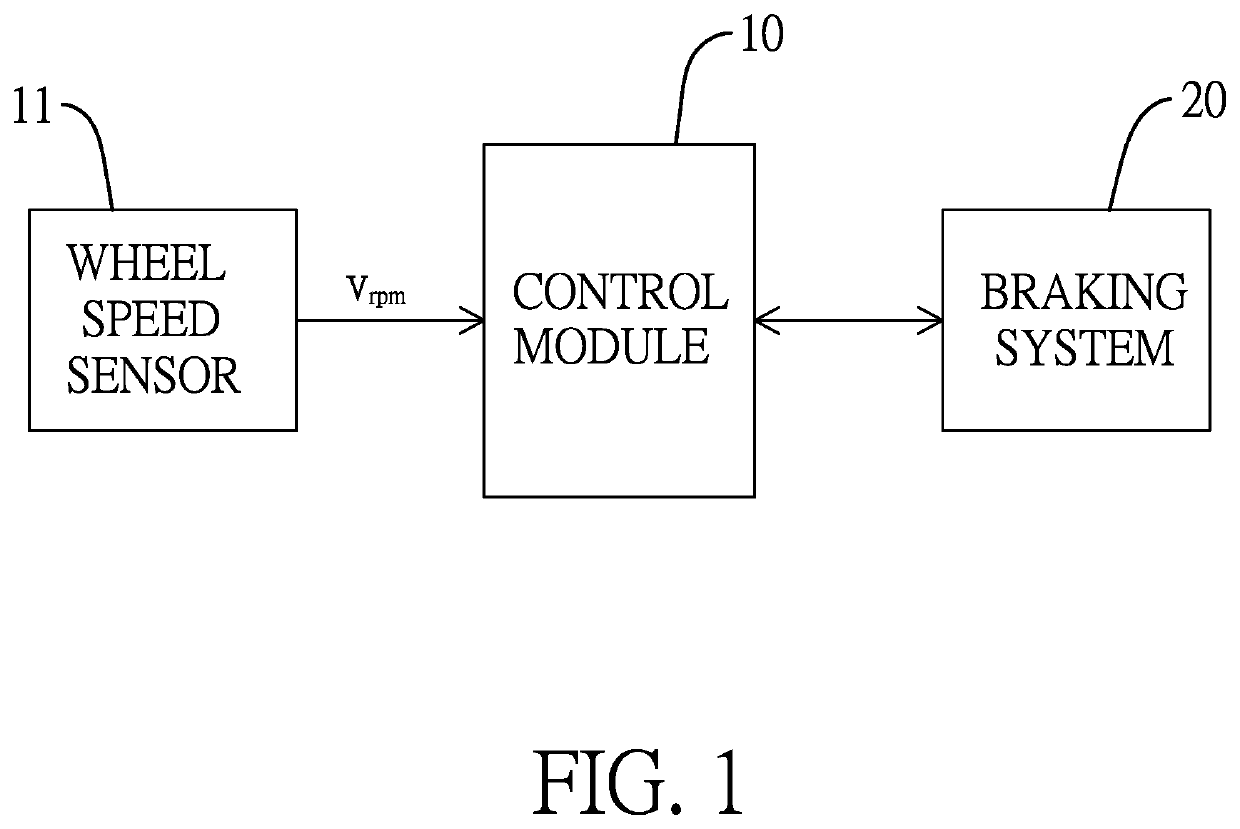
[0045]With reference to FIG. 1, an anti-lock braking system (ABS) essentially comprises a control module 10 and a wheel speed sensor 11 electrically connected to the control module 10. The control module 10 is electrically connected to a braking system 20 of a vehicle (such as a car, a truck, a scooter, and so on) for signal transmission. The control module 10 receives a signal vrpm of wheel speed from the wheel speed sensor 11 wherein the signal vrpm of the wheel speed is a number of revolutions of the wheel per minute detected by the wheel speed sensor 11. The control module 10 will compute a real-time wheel speed vwheel according to the signal vrpm. The real-time wheel speed vwheel will be represented as:

vwheel=vrpm×2πr60×60×601000(kilometerhour)

[0046]In the above equation, r is a radius of the wheel and a unit of the radius is meter (m). The unit of the real-time wheel speed vwheel is kilometers-per-hour.

[0047]In general, after the vehicle is started, the control module 10 will...


PUM


Abstract

A braking control method according to friction of road surface includes computing a real-time wheel speed according to a signal received from a wheel speed sensor; storing the real-time wheel speed as a wheel initial velocity when a braking event occurs; determining a relative-peak value according to the real-time wheel speed; estimating a vehicle deceleration according to the relative-peak value and the wheel initial velocity; computing an adjustment parameter according to the vehicle deceleration and a tire slip threshold, wherein the adjustment parameter reflects friction coefficient of road surface; and adjusting time length of an enhancement stage in an enhance-pressure control period of a stepped pressure-increasing phase according to the adjustment parameter; or adjusting time length of a reduction stage in a reduce-pressure control period of a stepped pressure-decreasing phase according to the adjustment parameter.

Description

BACKGROUND OF THE INVENTION1. Field of the Invention[0001]The present application relates generally to a braking control method, and more particularly to a braking control method according to friction of road surface.2. Description of Related Art[0002]Vehicle technology has been focused on Advanced Driver Assistance System (ADAS) for a long time. The purpose of ADAS is to assist the driver in driving the vehicle (such as a car, a truck, a scooter, and so on). ADAS will protect the driver, the passengers, people on the roads, and road facilities from dangers or damages.[0003]For example, with reference to FIG. 8, a conventional Electronic Stability Control system (ESC) comprises a control module 30 and multiple sensors connected to the control module 30. The multiple sensors will include a wheel speed sensor 31, an accelerometer 32, a steering angle sensor 33, and a yaw-rate sensor 34. The control module 30 will be electrically connected to the powertrain system 40, the steering syst...

Claims


Application Information

Patent Timeline
Patent Type & Authority Applications(United States)
IPC IPC(8): B60T8/1763B60T8/32B60W40/068B60W10/18
CPCB60T8/1763B60T8/329B60W40/068B60W2520/26B60T2210/12B60T2240/03B60W2520/28B60W10/18B60T8/17636B60W2710/182
Inventor LIN, HSIN-CHUANWEI, JIA-LE
Owner AUTOMOTIVE RES & TESTING CENT
Why Eureka
Try Eureka