Eureka AIR delivers breakthrough ideas for toughest innovation challenges, trusted by R&D personnel around the world.

Work hood

a technology for working hoods and hoods, applied in lighting and heating apparatus, ventilation systems, heating types, etc., can solve problems such as insufficient workability, and achieve the effects of wider work area, and readily and completely decontaminated

Active Publication Date: 2021-06-03
AIREX
View PDF4 Cites 0 Cited by
  • Summary
  • Abstract
  • Description
  • Claims
  • Application Information

AI Technical Summary

Benefits of technology

The present invention provides a work hood with a rotation support that can rotate the entire half suit, resulting in a wider work area for the worker. The rotation support includes a base portion, a rotating portion, a bearing portion, a sealing member, and a communication hole. The sealing member is annularly provided over the whole periphery of the rotation support to separate the work box and the external environment. The communication hole allows for the supply of clean air, decontamination gas or mist to the inside of the small space. The bearing portion can include a large bearing or multiple small bearings to support the entire half suit. The sealing member can be projected onto the wall surfaces of the base portion and the rotating portion, and the control mechanisms can be activated to change the height of the sealing member to come into contact with the wall surface. These technical features improve the efficiency and safety of the work hood.

Problems solved by technology

Nonetheless, the glove box system provides a limited work area, and its fixed glove position restricts the movement of worker's arms, resulting in insufficient workability.

Method used


Image

  • Work hood
  • Work hood
  • Work hood

Examples


first embodiment

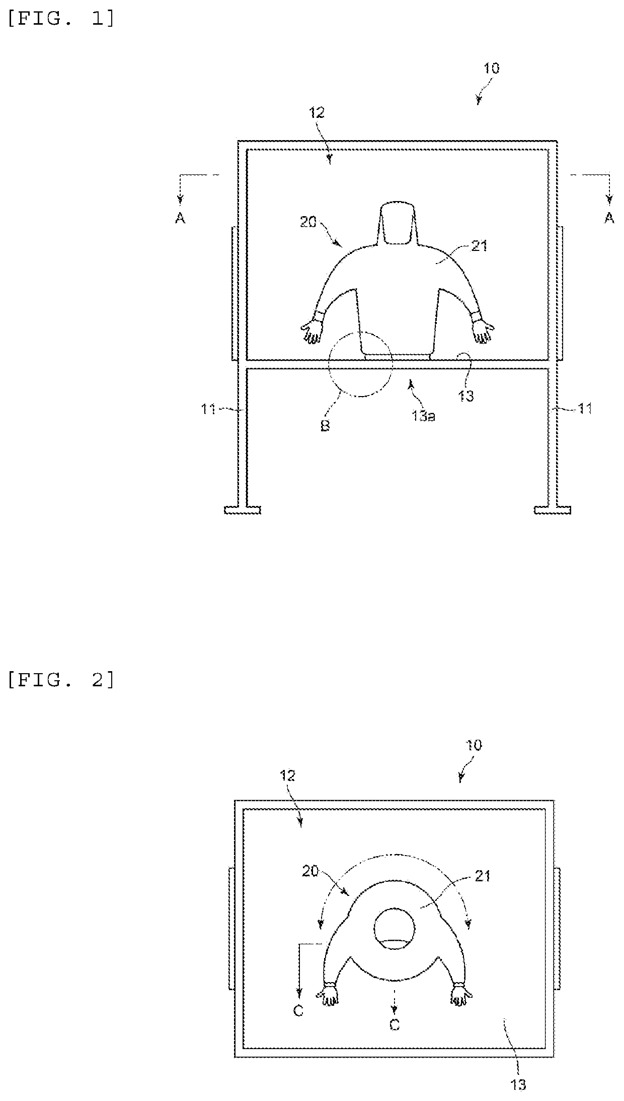
[0066]A first embodiment of the work hood according to the present invention will be described with reference to the drawings. FIG. 1 is a schematic cross-sectional view showing an isolator including a work hood viewed from the front. FIG. 2 is a schematic cross-sectional view (taken along the line A-A of FIG. 1) showing the isolator viewed from the top. In FIGS. 1 and 2, an isolator 10 is composed of leg portions 11 placed on the floor, a work box (chamber) 12 placed on the leg portions 11, and a work hood 20 including a hollow half suit 21 connected at an circular opening 13a formed at a bottom wall portion 13 inside the chamber 12 and projecting into the inside of the chamber 12. In FIG. 2, the work hood 20 is rotatable horizontally at any angle including 360°.

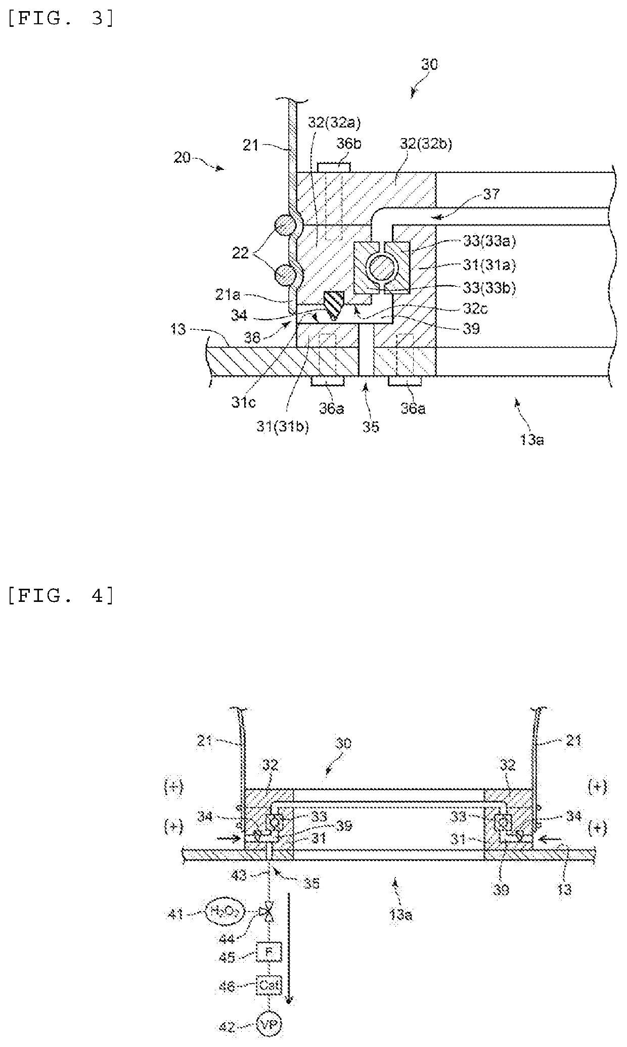
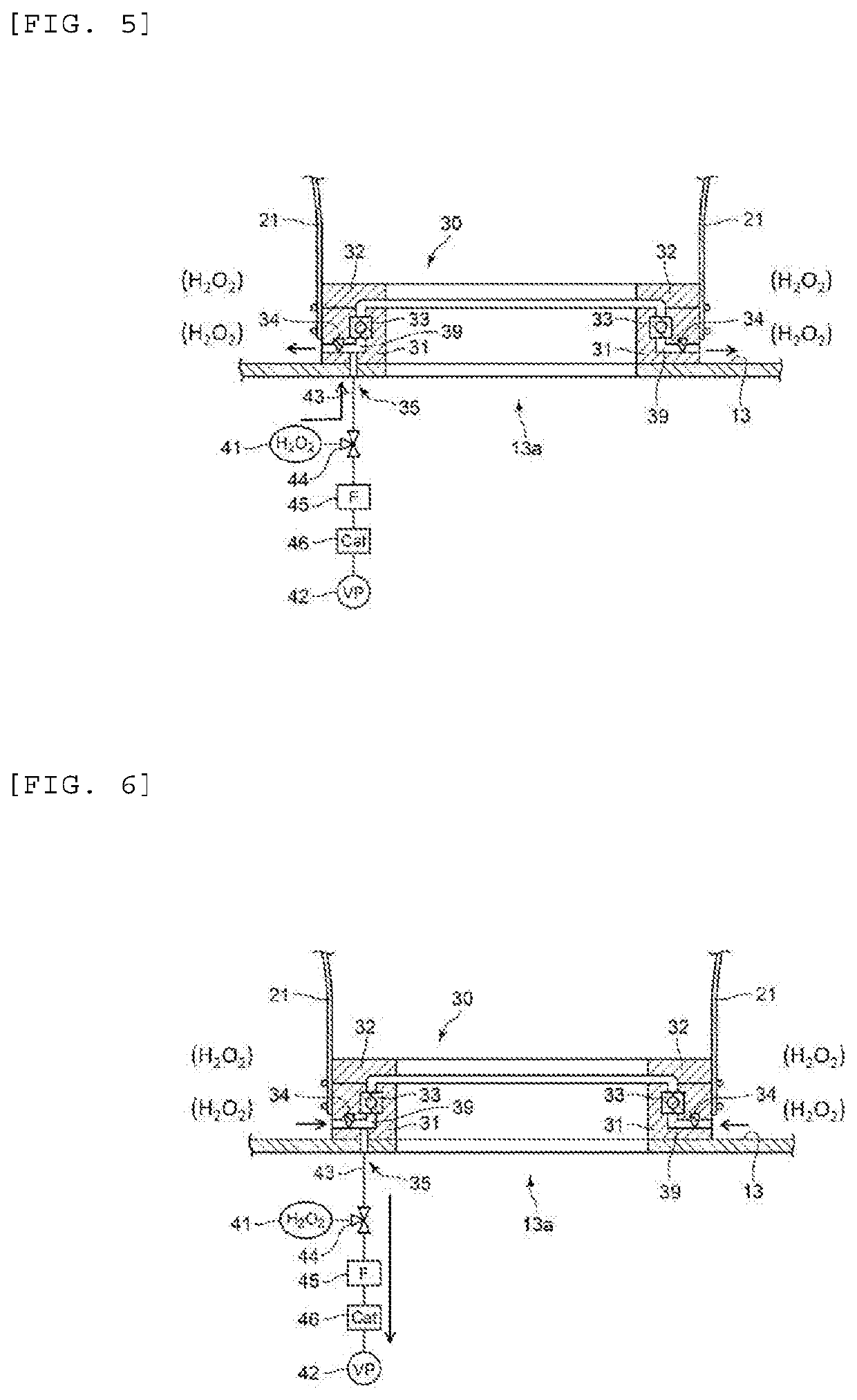
[0067]Subsequently, the configuration of a rotation support for allowing the work hood to rotate will be described. FIG. 3 is a cross-sectional view (taken along the line C-C of FIG. 2 at Part B in FIG. 1) showing the confi...

second embodiment

[0084]A second embodiment of the work hood according to the present invention will be described with reference to the drawings. In this second embodiment, the position and number of communications holes leading to the external environment from a small space are different from those in the first embodiment. FIG. 7 is a cross-sectional view (taken along the line C-C of FIG. 2 at Part B in FIG. 1) showing the configuration of a rotation support included in the work hood. FIG. 8 is a schematic cross-sectional view showing the relationship between a small space and a communication hole in the second embodiment viewed from the top.

[0085]In FIG. 7, a work hood 120 is connected around a circular opening 13a formed at a bottom wall portion 13 inside a chamber 12 by an annular rotation support 130. The rotation support 130 includes a base portion 131, a rotation portion 132, a bearing portion 133, a lip seal 134, and a communication hole 135. The configurations of the base portion 131, the ro...

third embodiment

[0089]A third embodiment of the work hood according to the present invention will be described with reference to the drawings. In this third embodiment, the configuration of a rotating portion of a rotation support is different from that in the above first embodiment. FIG. 9 is a cross-sectional view (taken along the line C-C of FIG. 2 at Part B in FIG. 1) showing the configuration of a rotation support included in the work hood in the third embodiment.

[0090]In FIG. 9, a work hood 220 is connected around a circular opening 13a formed at a bottom wall portion 13 inside a chamber 12 by an annular rotation support 230. The rotation support 230 includes a base portion 231, a rotation portion 232, a bearing portion 233, a lip seal 234, and a communication hole 235. The configurations of the base portion 231, the bearing portion 233, the lip seal 234, and the communication 235 are identical to those in the above first embodiment.

[0091]In FIG. 9, the rotating portion 232 is an L-shaped ann...


PUM


Abstract

The present invention provides a work hood that allows for free rotation in a work box to provide a wide work area and easy decontamination of a sealing portion present at the boundary between the work hood and the work box.A rotation support for rotatably supporting the entire half suit is provided. The rotation support includes a base portion, a rotating portion, a bearing portion, a sealing member, and a communication hole. The base portion is airtightly and annularly provided around an opening, and the rotating portion is provided around the base portion through the bearing portion, with a hem portion of the half suit being fixed to the rotating portion. The sealing member is annularly provided in an annular space formed by the base portion and the rotating portion so as to separate the work box and the external environment. The communication hole is provided so as to lead to the external environmental side from the annular small space side formed by the sealing member together with the base portion, the rotating portion, and the bearing portion, and is connected to a supply means for supplying a decontamination gas and the like to the inside of the small space and to a suction means for sucking clean air and the like from the inside of the small space.

Description

TECHNICAL FIELD[0001]The present invention relates to a work hood used in environments requiring high air cleanliness for separating a worker from the environment.BACKGROUND ART[0002]In a work at a manufacturing or research and development stage of pharmaceutical products, environments requiring high air cleanliness such as a clean room and a dust-free room must be prepared. Specifically, workers often fill such pharmaceutical products into a sterile container manually, and potential work environment contamination is prevented by employing a work box operated in a sterile / dust-free state. Conversely, works for handling materials harmful to the human body and the like involve the use of work boxes sealed in operation to protect a worker from a contaminated environment. What is employed in these work boxes for a worker to perform a work is a glove box system using a glove from an outside of the work box or a work hood system using a work hood such as a half suit with the upper body pr...

Claims


Application Information

Patent Timeline
Patent Type & Authority Applications(United States)
IPC IPC(8): F24F3/163F24F7/06B01L1/04
CPCF24F3/163B01L1/04F24F7/06B01L1/025B25J21/02B01L2200/0689B01L2200/087B01L2200/141B01L2200/082B01L2200/026F16J15/40B08B15/026B01L1/00B08B15/023F16J15/18F16J15/3248A41D13/02A41D2200/20
Inventor KAWASAKI, KOJIKAKUDA, DAISUKEMASUDOME, JUNKINBARA, TAKASHIKITAHORA, KAZUHIKONAGAI, KENIMAI, HIROYUKIHAYASHI, TAKUYA
Owner AIREX
Why Eureka
Eureka Blog
Learn More