Light extraction apparatus and flexible OLED displays

a technology of light extraction apparatus and flexible oled display, which is applied in the direction of organic semiconductor devices, solid-state devices, semiconductor devices, etc., can solve the problems of reducing the amount of oled-generated light available, reducing sharpness and contrast, etc., to improve the efficiency and peak brightness of the display, improve the out-coupling of light, and increase the external efficiency of flexible oled display

Inactive Publication Date: 2021-07-01
CORNING INC
View PDF15 Cites 0 Cited by
  • Summary
  • Abstract
  • Description
  • Claims
  • Application Information

AI Technical Summary

Benefits of technology

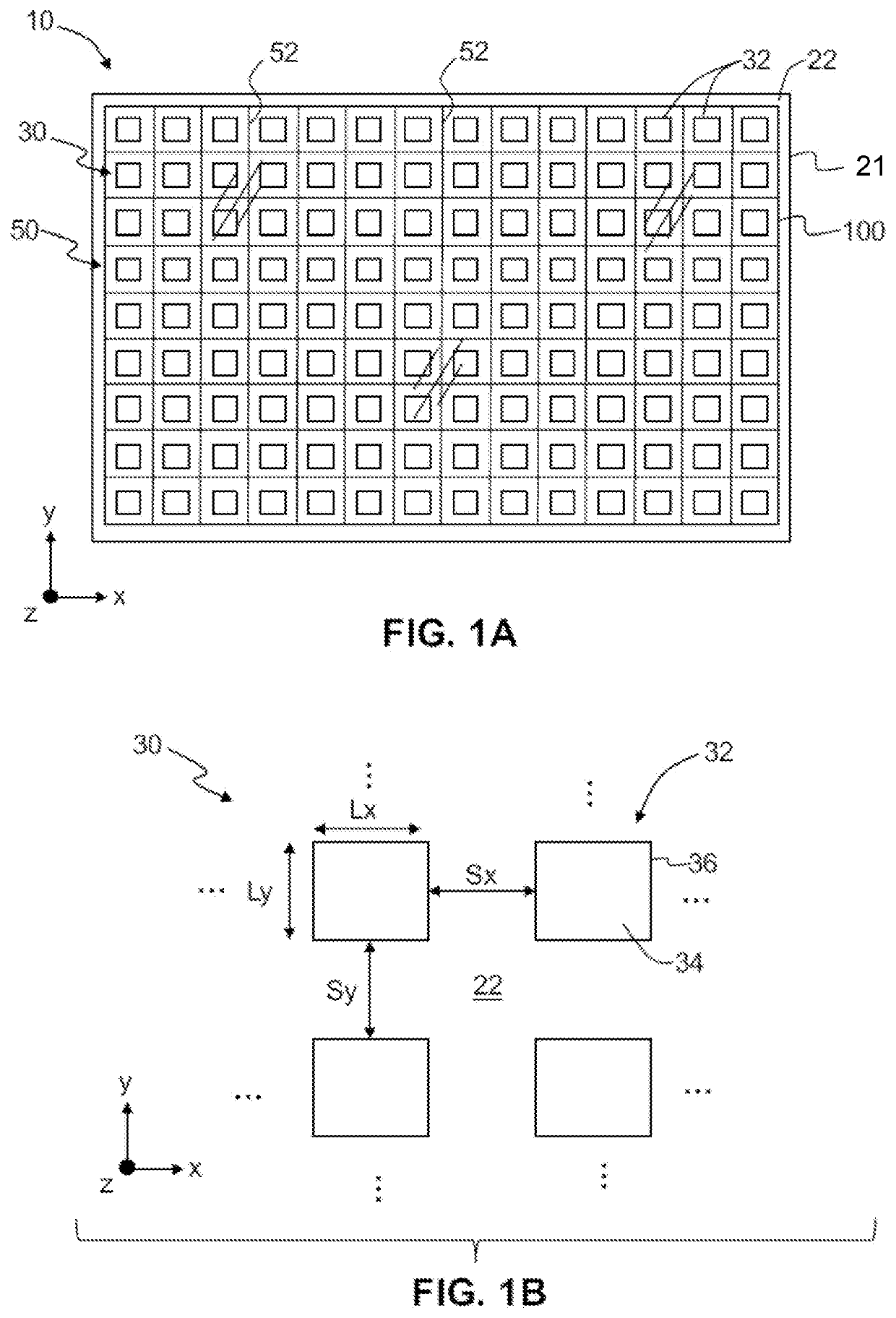
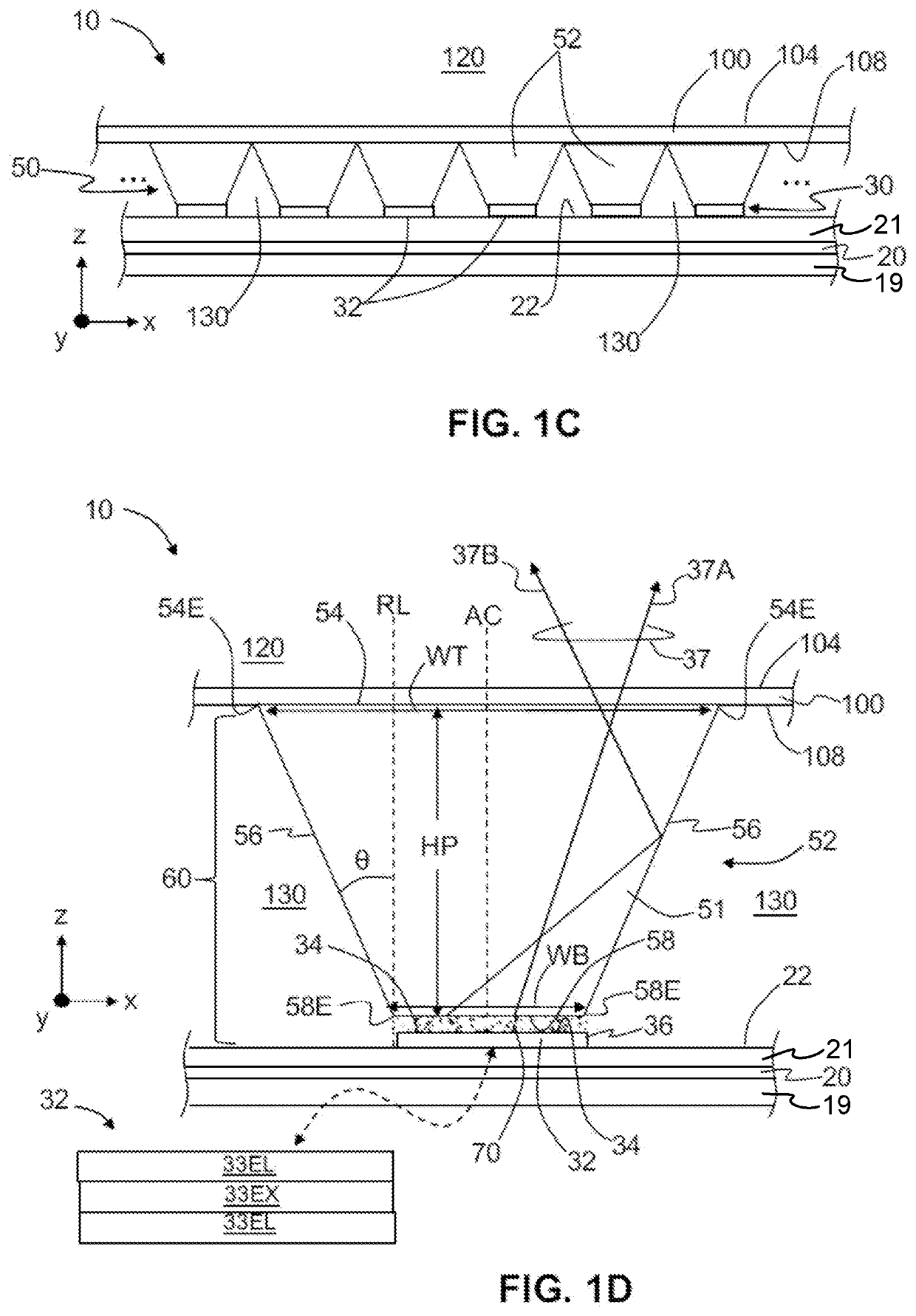
[0009]OLED displays including the light extraction apparatus disclosed herein significantly improve the out-coupling of light from the displays and increase the efficiency and peak brightness of the displays. The external efficiency of flexible OLED displays may be increased by a factor of 100% compared to displays not including the light extraction apparatus. Due to the increased external efficiency, the pixels of the display may be driven with less current for the same brightness, which increases the useful lifetime of the display and reduces the “burn-in” effect. Alternatively, or in addition, the pixels of the display may generate a higher peak brightness, which enables a high dynamic range (HDR). These capabilities are achieved while increasing the overall thickness of the displays by a few tens of microns, which leaves the displays flexible. In addition, the light extraction apparatus does not introduce optical scattering (i.e., haze) that can reduce sharpness and contrast. Further, the light extraction apparatus does not scramble the polarization state of light and is therefore compatible with the use of circular polarizers to reduce ambient light reflection.

Problems solved by technology

This further reduces the amount of OLED-generated light available for use in the OLED display.
In addition, the light extraction apparatus does not introduce optical scattering (i.e., haze) that can reduce sharpness and contrast.

Method used


Image

  • Light extraction apparatus and flexible OLED displays
  • Light extraction apparatus and flexible OLED displays
  • Light extraction apparatus and flexible OLED displays

Examples


Embodiment Construction

[0034]Reference will now be made in detail to embodiments of the present disclosure, examples of which are illustrated in the accompanying drawings. Whenever possible, the same reference numerals will be used throughout the drawings to refer to the same or like parts. However, this disclosure may be embodied in many different forms and should not be construed as limited to the embodiments set forth herein.

[0035]Ranges can be expressed herein as from “about” one particular value, and / or to “about” another particular value. When such a range is expressed, another embodiment includes from the one particular value and / or to the other particular value. Similarly, when values are expressed as approximations, by use of the antecedent “about,” it will be understood that the particular value forms another embodiment. It will be further understood that the endpoints of each of the ranges are significant both in relation to the other endpoint, and independently of the other endpoint.

[0036]Dire...


PUM

PropertyMeasurementUnit
light extraction efficiencyaaaaaaaaaa
temperatureaaaaaaaaaa
refractive indexaaaaaaaaaa

Abstract

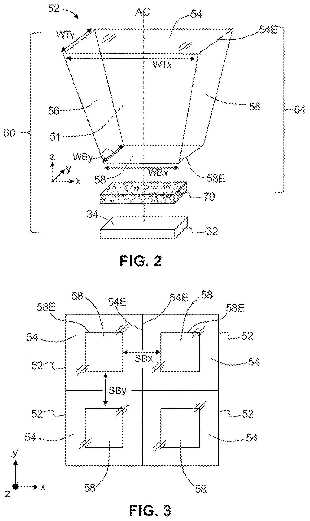
A light extraction apparatus includes a flexible substrate, an OLED supported by the flexible substrate, a flexible barrier film, a tapered reflector, and an index-matching layer. The tapered reflector includes at least one side surface, a top surface coupled to the flexible barrier film, and a bottom surface. The top surface is larger in surface area than the bottom surface. The index-matching layer is coupled between a top surface of the OLED and the bottom surface of the tapered reflector. Light emitted from the top surface of the OLED passes through the index-matching layer and into the tapered reflector. The at least one side surface of the tapered reflector includes a slope to redirect the light by reflection into an escape cone and out of the top surface of the tapered reflector.

Description

[0001]This application claims the benefit of priority under 35 U.S.C. § 119 of U.S. Provisional Application Ser. No. 62 / 673,281 filed on May 18, 2018 the content of which is relied upon and incorporated herein by reference in its entirety.BACKGROUNDField[0002]The present disclosure relates generally to organic light-emitting diode (OLED) displays. More particularly, it relates to flexible OLED displays and apparatus and methods for light extraction from flexible OLED displays.Technical Background[0003]OLEDs typically include a substrate, a first electrode, one or more OLED light-emitting layers, and a second electrode. OLEDs can be top-emitting or bottom-emitting. A top-emitting OLED may include a substrate, a first electrode, an OLED structure having one or more OLED layers, and a second transparent electrode. The one or more OLED layers of the OLED structure may include an emission layer and can also include electron and hole injection layers and electron and hole transport layers...

Claims


Application Information

Patent Timeline
Patent Type & Authority Applications(United States)
IPC IPC(8): H01L51/52H01L51/00H01L51/56
CPCH01L51/5271H01L51/0097H01L51/5275H01L2251/5338H01L51/56Y02E10/549H10K59/352H10K71/50H10K71/80H10K77/111H10K50/856H10K50/858H10K2102/311H10K71/00
Inventor BOWDEN, BRADLEY FREDERICKKUKSENKOV, DMITRI VLADISLAVOVICH
Owner CORNING INC
Why Eureka
Try Eureka