Downhole ratchet mechanism and method

Active Publication Date: 2021-07-08
KNJB INC
View PDF0 Cites 3 Cited by
  • Summary
  • Abstract
  • Description
  • Claims
  • Application Information

AI Technical Summary

Benefits of technology

[0030]The method further comprises the step of permitting slippage between the upper tubular of the drilling string and the lower tubular of the drilling string during the drilling operation to thereby dampen the rotational oscillations. The method may further comprise reconnecting the upper tubular to the lower tubular at least by when the lower tubular rotational velocity is greater than the upper tubular rotational velocity.
[0031]The present invention may also comprise a computer simulation of the damping effect of activating a slip mechanism, which could be of different types, depending on where the mounted in a drilling string where the rotational control may be operable for selectively transferring torque between tubulars in the drilling string, such as with an on-off type mechanism or a variable control. The method of the computer simulation may comprise one or more steps such as, for instance, providing parameter inputs for inputting drill string parameters describing the drilling string, providing one or more rotational control activation parameter for inputting conditions under which the rotational control is activated, and providing one or more outputs related to torsional oscillations of a drill bit (ratchet or drill string below ratchet) of the drilli

Problems solved by technology

Due to the torsional energy in the drilling string during drilling, oscillations of slowing and speeding of the drill bit can occur.
Full blown slip-stick results in the bit actually stopping and then when released, the bit begins spinning at high speeds sometimes much higher than the drilling speed.
Even at much lesser variations below full blown slip-stick, the drill string actually shortens and lengthens, which produces changes in the axial length of the drill string.
The shortening and lengthening of the drill string can cause poor cutting and damage to the bits.
Slip-stick is a problem that damages the bits as they are bounced up and down on the bottom of the wellbore (bit bounce), slowing drilling due to poor cutting during Slip-stick, increasing the number of bit trips, damaging the wellbore, causing an irregular well bore, causing circulation problems, decreasing the control of the direction of drilling, decreased cementing reliability due to the presence of one or more elongated troughs, clearance problems for gravel packing screens and other problems discussed below.
In some cases, full blown stick-slip at the lower portion of the drill string miles below the surface especially in higher angle holes or deeper holes is not readily detectable with surface sensors.
Therefore surface controls to vary drilling speed to counteract the stick-slip may not be effective.
Because modern PDC cutting elements of bits have a very short length and must be held in constant close contact with the surface to be cut for maximum cutting effects, even small axial changes in the length of

Method used


Image

  • Downhole ratchet mechanism and method
  • Downhole ratchet mechanism and method
  • Downhole ratchet mechanism and method

Examples


Embodiment Construction

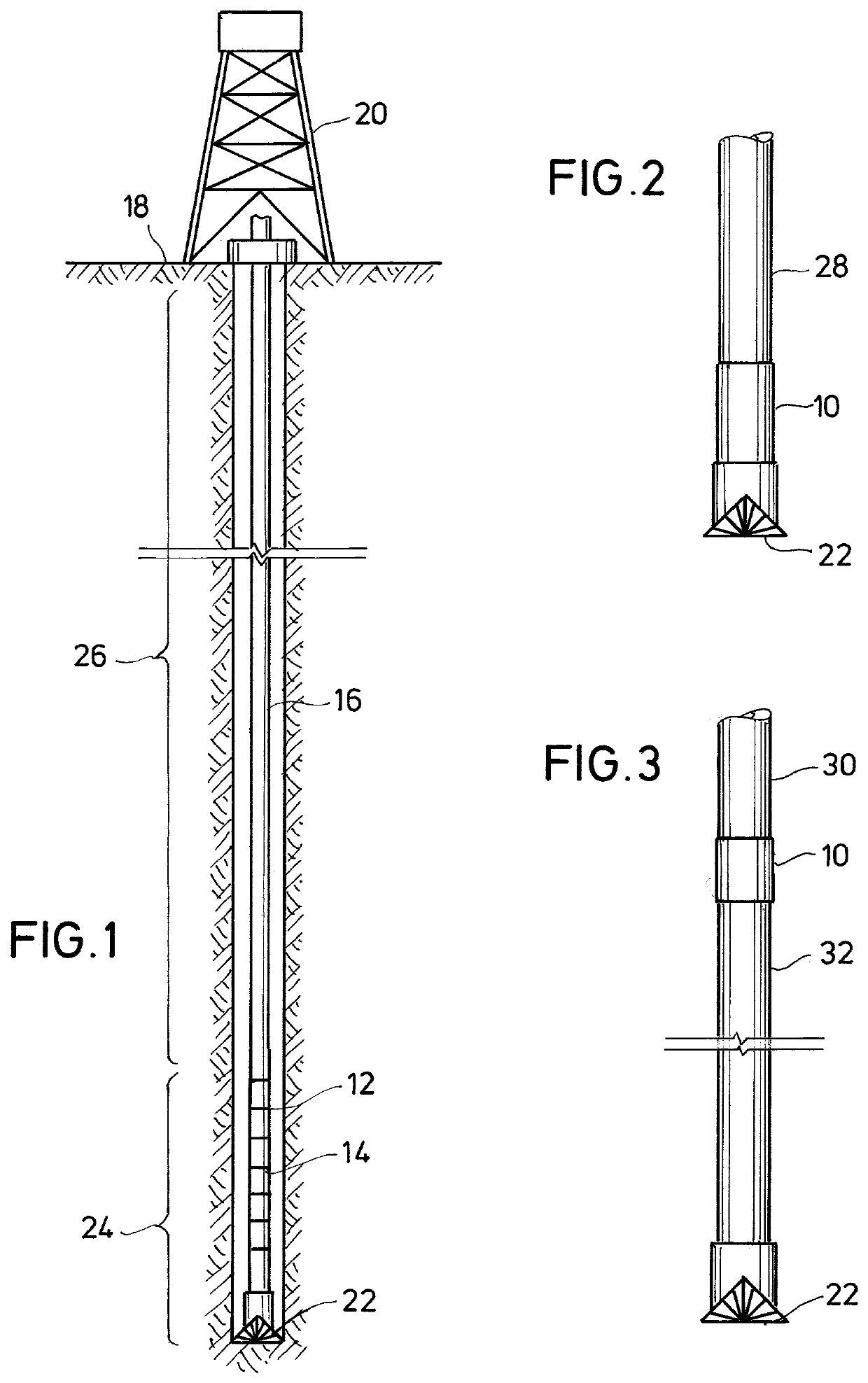
[0050]FIG. 1 shows one or more slip mechanisms 10 as described below mounted at various positions 12, 14 in the drill string 16. In other words, the present invention may use a plurality of slip mechanisms inserted at strategic positions or may use a single slip mechanism 10 for insertion at a strategic position as discussed herein. Slip mechanisms may also be referred to herein as ratchet mechanisms, clutches, or the like. There may be only one slip mechanism, but due to the low cost of some embodiments, it would also be possible to use more than one. The drill string 16 extends from an earth surface 18 to the drill bit 22. Surface drive 20 applies torque to rotate the drill sting to rotate the bit. Alternatively, the bit 22 may be driven by a downhole motor.

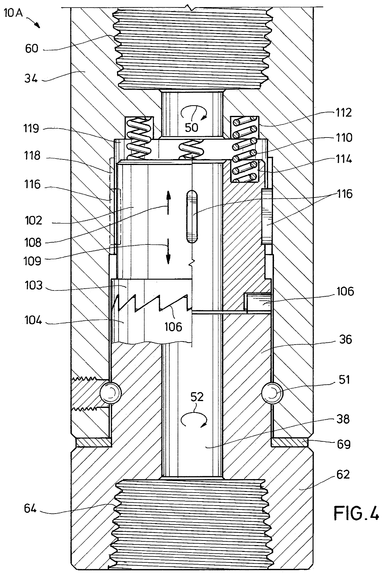
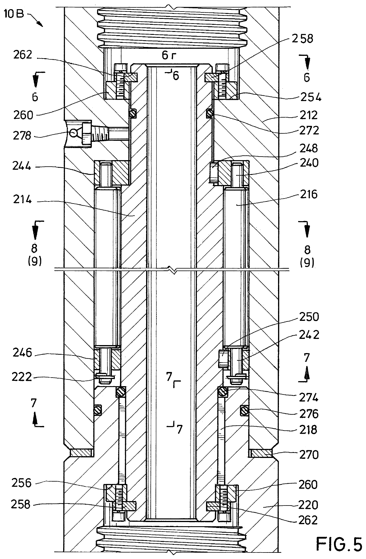
[0051]Various embodiments of a slip mechanism are shown in FIGS. 4, 5, and 12. The slip mechanisms allow rotation of an inner member with respect to an outer member when the inner member spins faster than the outer member. Othe...


PUM


Abstract

A slip mechanism is utilized between tubulars in the drill string to reduce torsion energy in the drill string. The slip mechanism is connected to release when the tubular below the slip mechanism spins faster than the tubular above the slip mechanism. When the tubular below spins more slowly or at the same speed then the slip mechanism firmly secures the upper and lower tubulars together to rotate the bit. The effect is to release torsional energy in the drill string to reduce and eliminate slip stick oscillations. A computer is programmed to determine an optimal position in the drill string to release the torsional energy in the drill string.

Description

BACKGROUND OF THE INVENTIONField of the Invention[0001]The present invention relates generally to a downhole slip mechanism for drill string that allows torsion energy in the drill string to be released and more particularly to a slip mechanism with that slip to release torsion in the drill string.Description of the Background[0002]Slip-stick (stick-slip) occurs when the bit grabs the formation and then releases. Due to the torsional energy in the drilling string during drilling, oscillations of slowing and speeding of the drill bit can occur. Full blown slip-stick results in the bit actually stopping and then when released, the bit begins spinning at high speeds sometimes much higher than the drilling speed. The oscillation can continue indefinitely. Even at much lesser variations below full blown slip-stick, the drill string actually shortens and lengthens, which produces changes in the axial length of the drill string. The shortening and lengthening of the drill string can cause ...

Claims


Application Information

Patent Timeline
IPC IPC(8): E21B44/04E21B7/04
CPCE21B44/04E21B17/1078E21B7/04E21B12/00
Inventor NASH, KENNETH LKUENZEL, RAINER
Owner KNJB INC
Why Eureka
Try Eureka