

Wind turbine with blades hinged at an intermediate position
a technology of wind turbines and intermediate positions, applied in the direction of wind motors, wind motor control, motors, etc., can solve the problems of extensive downtime, maintenance of controllers and mechanical parts,
Pending Publication Date: 2021-07-08
VESTAS WIND SYST AS
View PDF9 Cites 2 Cited by
- Summary
- Abstract
- Description
- Claims
- Application Information
AI Technical Summary
Benefits of technology
The invention is a wind turbine with blades that fold inward when the wind is strong or the turbine is spinning quickly. The blades are designed to capture energy from the wind effectively. Additionally, the amount of material used for the blades is reduced compared to other wind turbines.
Problems solved by technology
Such controllers and mechanical parts require maintenance.
This may be difficult in the case that the wind turbine is positioned at a remote location.
In this case failure or breakdown may lead to extensive downtime, e.g. due to long transportation time for maintenance personnel or long delivery time on spare parts.
Method used
View moreImage
Smart ImageViewing Examples

Examples
first embodiment
[0077]FIGS. 10 and 11 illustrate a hinge for a wind turbine blade of a wind turbine according to the invention,
second embodiment
[0078]FIGS. 12 and 13 illustrate a hinge for a wind turbine blade of a wind turbine according to the invention, and
[0079]FIGS. 14-16 are side views of wind turbines according to three embodiments of the invention.
Login to View More PUM
 Abstract
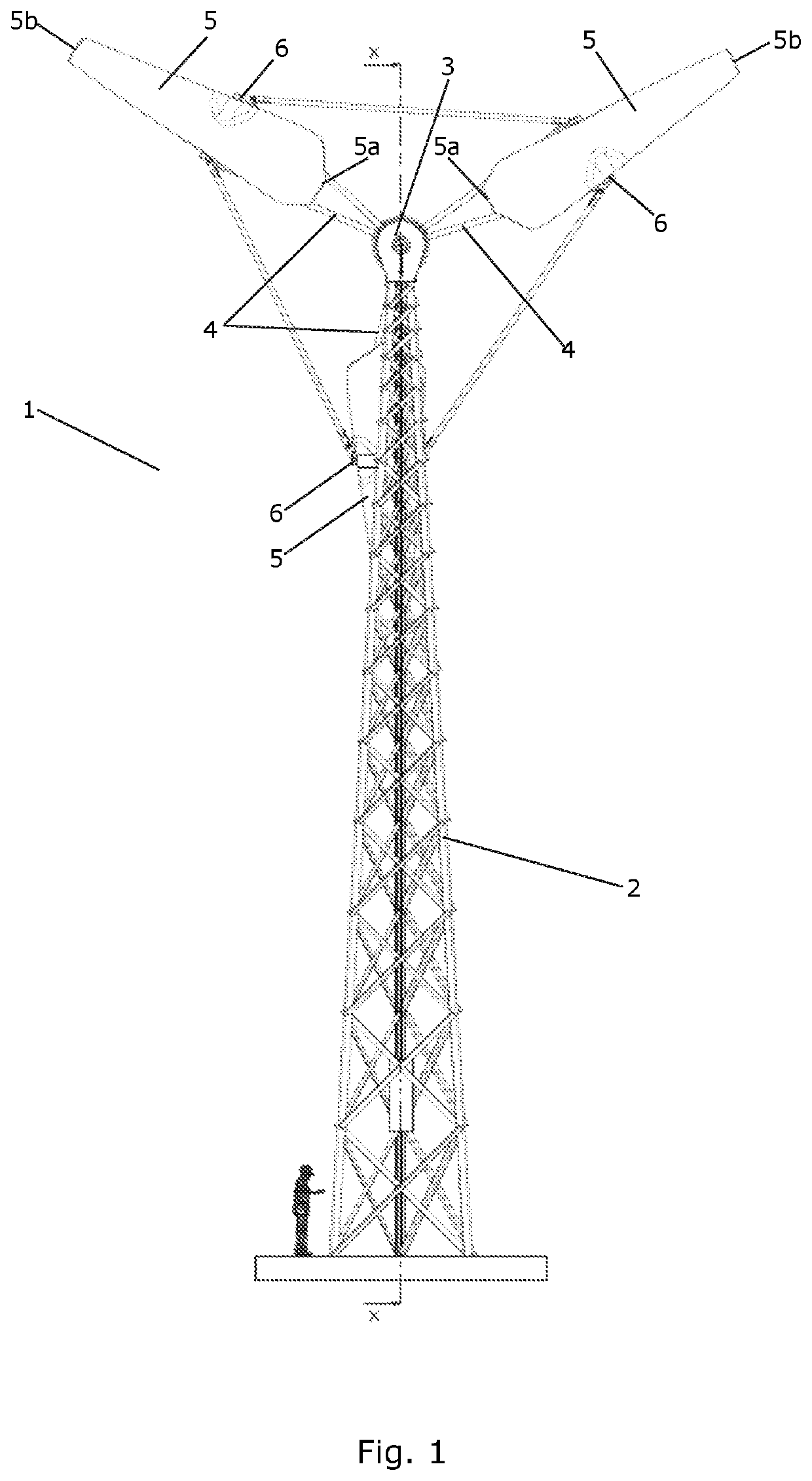
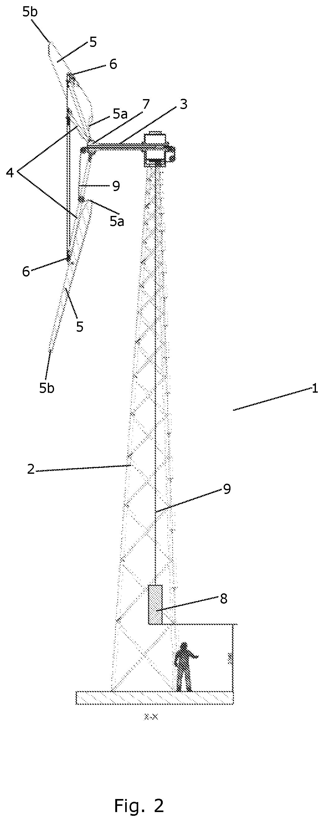
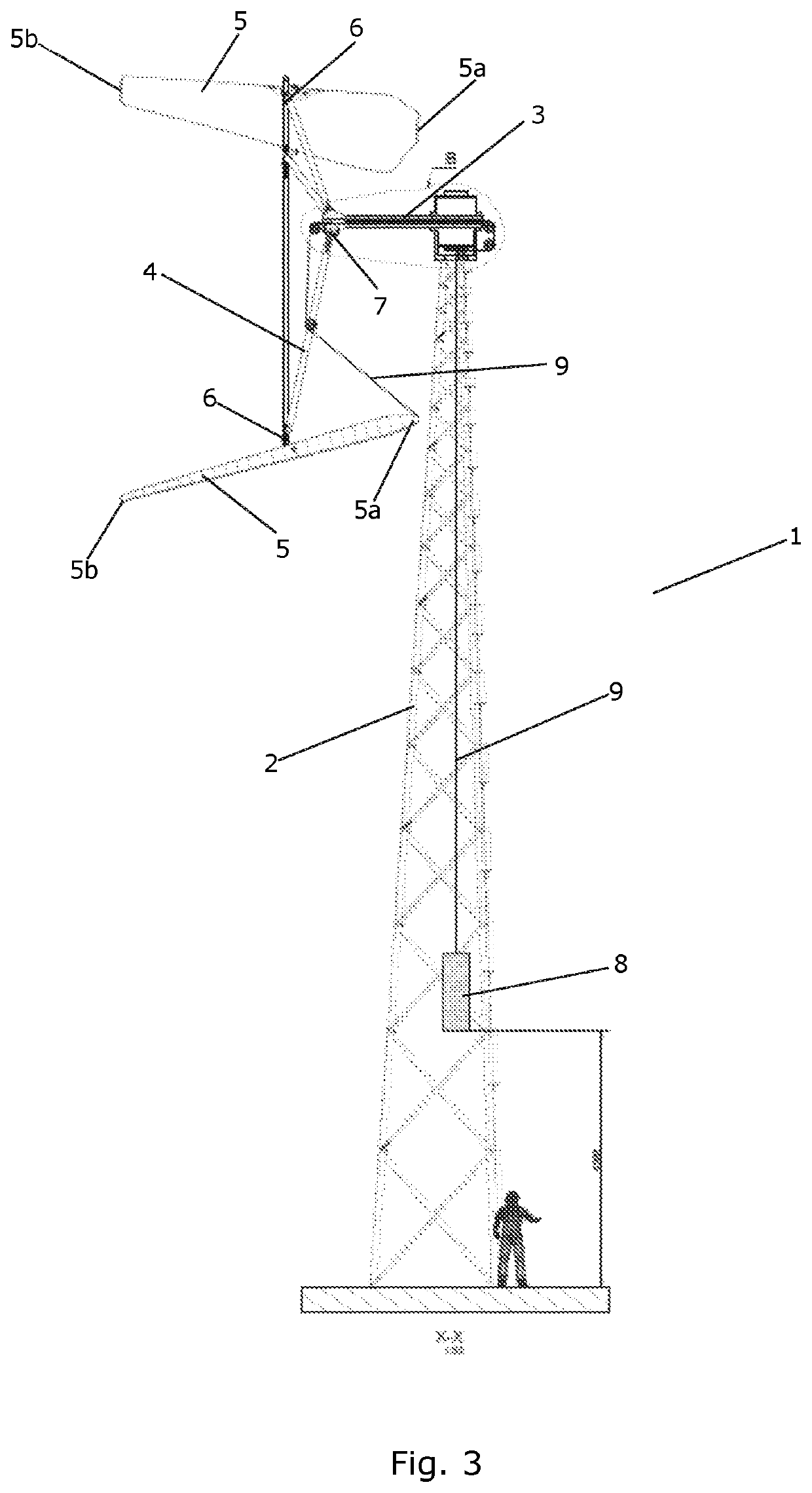
A wind turbine (1) comprising a tower (2), a nacelle (3) and a hub (7) is disclosed. The hub (7) comprises a blade carrying structure (4) with one or more wind turbine blades (5) connected thereto. Each of the wind turbine blades (5) defines an aerodynamic profile having a chord which varies along a length of the wind turbine blade (5). Each of the wind turbine blades (5) is connected to the blade carrying structure (4) via a hinge (6) at a hinge position of the wind turbine blade (5), each wind turbine blade (5) thereby being arranged to perform pivot movements relative to the blade carrying structure (4) between a minimum pivot angle and a maximum pivot angle. The hinge position is arranged at a distance from the inner tip end (5a) and at a distance from the outer tip end (5b), and the chord at the hinge position is larger than or equal to the chord at the inner tip end (5a) and larger than the chord at the outer tip end (5b).
Description
FIELD OF THE INVENTION[0001]The present invention relates to a wind turbine comprising a tower, a nacelle and a hub comprising a blade carrying structure. One or more wind turbine blades are pivotally connected to the blade carrying structure via hinges.BACKGROUND OF THE INVENTION[0002]Wind turbines are normally controlled in order to provide a desired power output and in order to control loads on the wind turbine. For horizontal axis wind turbines, i.e. wind turbines with a rotor which rotates about a substantially horizontal rotational axis, this may be obtained by controlling a pitch angle of the wind turbine blades. In this case the angle of attack of the wind turbine blades relative to the incoming wind is adjusted by rotating the wind turbine blades about a longitudinal axis.[0003]Traditional pitch control as described above requires sensor based controllers as well as mechanical parts, e.g. in the form of pitch bearings and drive units. Such controllers and mechanical parts r...
Claims
Login to View More Application Information
Patent Timeline
 IPC IPC(8): F03D7/02F03D1/06
CPCF03D7/0236F03D1/0625F05B2240/2022F03D7/0264F03D7/0244F03D1/0658F05B2240/313Y02E10/72
Inventor NIELSEN, THOMAS S. BJERTRUPANDERSEN, PETER BJØRN
Owner VESTAS WIND SYST AS