
Wearable device for the detection of cardiac signals, a system comprising said device and a relative method of operation

a wearable device and cardiac signal technology, applied in the field of wearable devices for detecting cardiac signals, can solve the problems of limiting the number, non-diagnosis of acute ischaemic events/myocardial infarctions, and the inability to calculate any of the three bipolar leads di-diii or any of the unipolar precordial wilson leads vb>1/b>-vb>6/b>, so as

Pending Publication Date: 2021-07-15
POLICARDIO SRL
View PDF0 Cites 2 Cited by
  • Summary
  • Abstract
  • Description
  • Claims
  • Application Information

AI Technical Summary

Benefits of technology

The present invention aims to provide a device that is easy for patients to use and accurately measures the data. It also aims to provide a method for operating the system to perform a linear transformation for cardiac leads, which minimizes errors and differences between patients.

Problems solved by technology

For this reason, limiting the number of leads available to medical personnel may result in the non-diagnosis of acute ischaemic events / myocardial infarctions.
However, due to the actual non-homogeneity of the thorax, the calculation of any of the three bipolar leads DI-DIII or any of the unipolar precordial Wilson leads V1-V6 by linear transformation of other measured leads is not always applicable.
Moreover, from an experimental point of view, alternative electrode configurations may be subject to greater noise, and therefore not all the configurations are possible.
However, this approach has the following drawbacks:the finite element model does not take into account patient-specific differences, as it is built with the parameters of an average thorax; however, as is well known, an individual patient's thorax can have very different dimensions from the average, as there is a high interpersonal variability;the finite element model does not further take into account patient-specific differences regarding the composition of the body of the individual patient, that is, in terms of the percentage of fat mass, lean mass, or the dimensions of the lungs;the positioning of the electrodes may be different from the ideal positioning with which the model has been constructed, introducing an additional error factor.
Moreover, as is known, finite element models are built by highly specialised engineers, and therefore, if one wanted to calculate a transformation suitable for a particular category of patients, or obtain a patient-specific transformation, the time and cost to derive such a transformation would be extremely great.
These systems are particularly compact, however, they may not be sufficient for identifying problems associated with the heart for the reasons outlined above.

Method used


Image

  • Wearable device for the detection of cardiac signals, a system comprising said device and a relative method of operation
  • Wearable device for the detection of cardiac signals, a system comprising said device and a relative method of operation
  • Wearable device for the detection of cardiac signals, a system comprising said device and a relative method of operation

Examples


Embodiment Construction

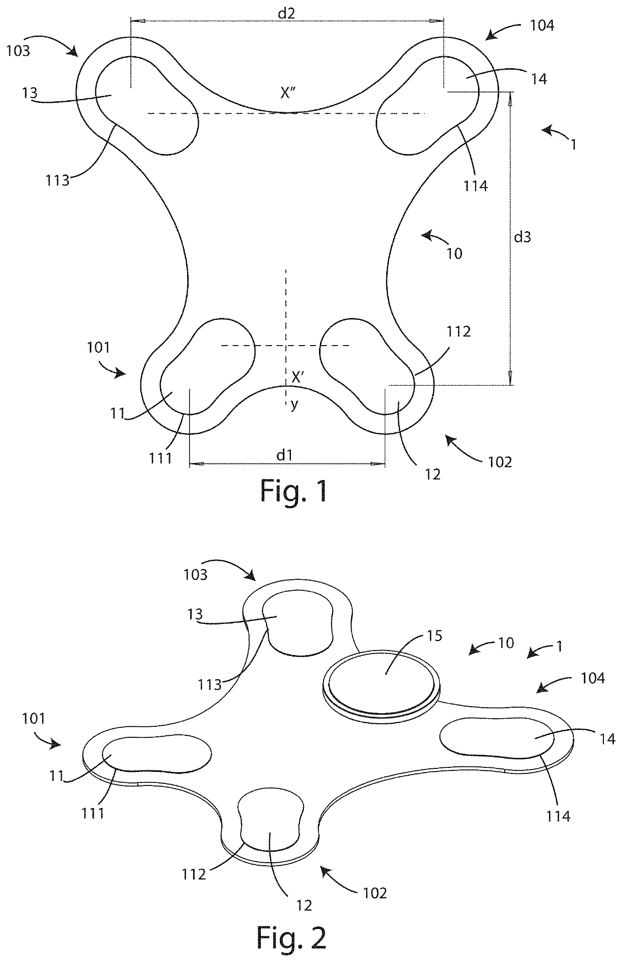
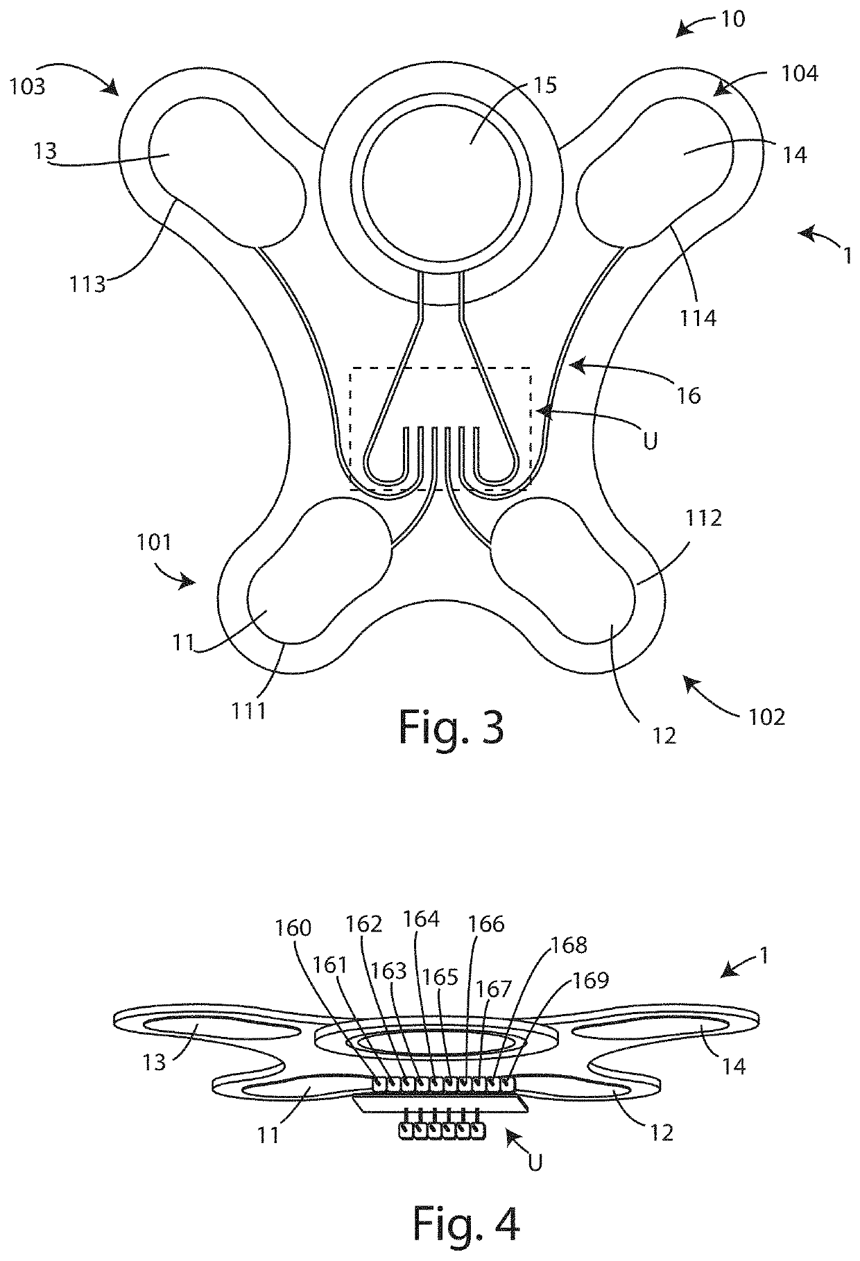
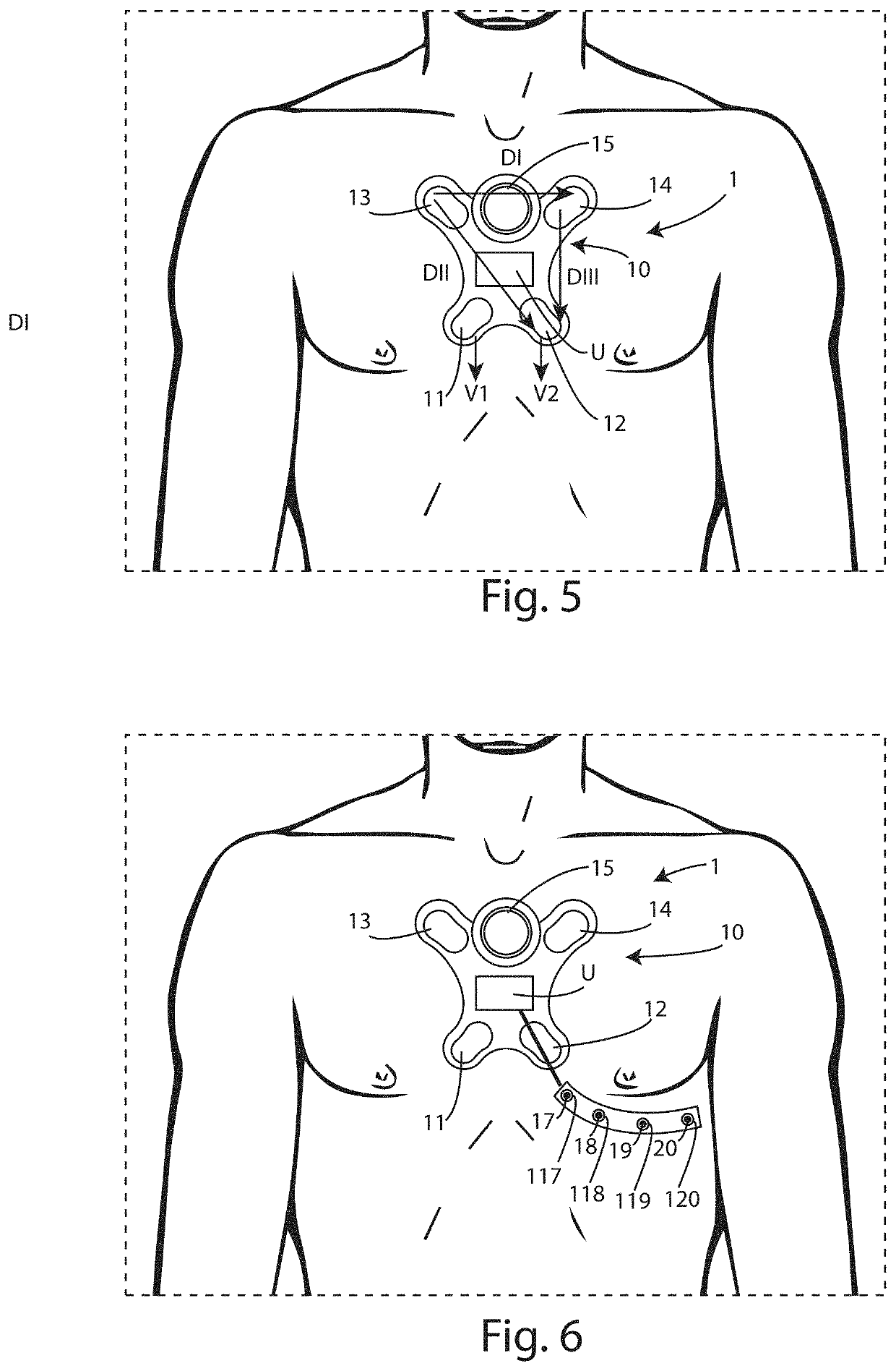
[0110]With particular reference to FIGS. 1-5, reference numeral 1 denotes a device for detecting cardiac electrical signals according to the invention.

[0111]In particular, the detection device 1 is configured to detect at least five leads of the cardiac electrical dipole vector, including three bipolar leads DI′, DII′, DIII′ and two unipolar leads V1′, V2′, by means of four electrodes 11, 12, 13, 14, as described below.

[0112]Preferably, the detection device 1 is configured to detect eight leads of the cardiac electrical dipole vector, comprising the five leads described above plus three augmented leads of the limbs aVR′, aVF′, aVL′.

[0113]Moreover, the detection device 1 can be integrated inside a system 100 comprising a data receiving device 2, preferably remotely accessible and configured to interact with further peripheral units, as described below.

[0114]In particular, the detection device 1 comprises a supporting element 10 for structural support of the device 1, comprising:

[0115...


PUM


Abstract

Described is a detection device (1) for detecting cardiac electrical signals, wearable by a patient, comprising a right lower electrode (11) and a left lower electrode (12), for detecting cardiac electrical potentials, positioned in alignment with each other on a first horizontal axis (x′), spaced apart from each other by a first distance (d1); a right upper electrode (13) and a left upper electrode (14), for detecting cardiac electrical potentials, positioned above said lower electrodes (11, 12), and being aligned with each other on a second horizontal axis (x″), parallel to said first horizontal axis (x′), and spaced from each other by a second distance (d2), greater than or equal to said first distance (d1); and a logic control unit (U), electrically connected to said electrodes (11, 12, 13, 14), wherein said logic control unit (U) is configured to receive a first bipolar lead (DI′), detected between said left upper electrode (14) and said right upper electrode (13); a second bipolar lead (DII′), detected between said left lower electrode (12) and said right upper electrode (13); a third bipolar lead (DIII′), detected between said left lower electrode (12) and said left upper electrode (14); a first unipolar lead (V1′), detected between said right lower electrode (11) and a first average potential, and a second unipolar lead (V2′), detected between said left lower electrode (12) and said first average potential, wherein said first average potential is equal to the average of detected signals, with respect to a reference potential, on said right upper electrode (13), on said left upper electrode (14) and on said left lower electrode (12). The invention also relates to a system comprising said device and a relative method of operation.

Description

RELATED APPLICATION[0001]This application claims the benefit of priority of Italian Patent Application No. 102020000000451 filed on Jan. 13, 2020, the contents of which are incorporated herein by reference in their entirety.FIELD AND BACKGROUND OF THE INVENTION[0002]This invention relates to a wearable device for detecting cardiac signals.[0003]The invention also relates to a system comprising said device.[0004]The invention also relates to the method of operation of said device and of said system.[0005]More specifically, the invention relates to a wearable and portable device for detecting cardiac electrical signals, and the relative system and method.[0006]As is known, electrocardiography studies the electrical activity of the heart by modelling the heart muscle as an electrical dipole which varies in intensity and direction over time. In particular, this study is carried out by recording the electrical potential in the thorax and its variations using specially placed electrodes.[...

Claims


Application Information

Patent Timeline
Patent Type & Authority Applications(United States)
IPC IPC(8): A61B5/282A61B5/00A61B5/346
CPCA61B5/282A61B5/257A61B5/346A61B5/6823A61B5/0006A61B5/0245A61B5/6833A61B5/688A61B5/7203A61B5/7257A61B5/742A61B2560/0412A61B2560/0468A61B2562/046A61B2505/07A61B5/327A61B5/318A61B5/349A61B2562/0209
Inventor LONGO, MARCO
Owner POLICARDIO SRL
Learn More