System and method for coupling a hub to a main shaft of a wind turbine

a technology of wind turbines and hubs, which is applied in the field of wind turbines, can solve the problems of preventing personnel from entering the hub, affecting the safety of personnel, and a large amount of preload of threaded fasteners,

Active Publication Date: 2021-07-15
GENERAL ELECTRIC CO
View PDF0 Cites 1 Cited by
  • Summary
  • Abstract
  • Description
  • Claims
  • Application Information

AI Technical Summary

Benefits of technology

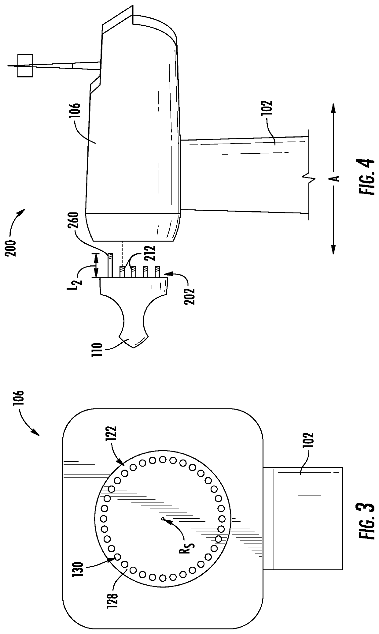
[0013]In another aspect, the present disclosure is directed to a mounting system for coupling a hub to a main shaft of the wind turbine. The mounting system may include a plurality of fasteners arranged within corresponding through holes arranged in a circular array about a rotational axis of the hub. Each of the plurality of fasteners may include a head section and a shank section. The head section may have a cross-sectional area greater than a cross-sectional area of the shank section. The shank section may have a first end and a second end disposed opposite thereof. The first end may define a first threaded portion configured to be received by the main shaft of the turbine. The mounting system may also include a connection mechanism securing the plurality of fasteners within the plurality of through holes so as to limit an axial translation of the plurality fasteners prior to the coupling of the hub to the main shaft. The connection mechanism may include a threaded portion of each of the through holes. The threaded portions may have a longitudinal length less than a longitudinal length of the through hole. The connection mechanism may also include a second threaded portion defined by the second end of the plurality of fasteners. The second threaded portion may be configured to engage the corresponding threaded portion of the through holes. The second threaded portion may be configured to resist a torque transmitted to the first threaded portion.

Problems solved by technology

As such, it is common to lose a significant amount of preload of the threaded fasteners due to the relaxation of the hub threads.
While employing through fasteners may eliminate the loss of preload due to the relaxation of the hub threads, the utilization of through fasteners may create additional challenges.
Because the hub is typically suspended a significant height above the ground during installation, safety limitations preclude personnel from entering the hub prior to its coupling to the main shaft.
As such, personnel are not available to insert and align the fasteners prior to the hub's coupling to the main shaft.
Additionally, not being permitted to enter the suspended hub may also preclude the ability of personnel to provide a counter torque to the fasteners during the coupling operation.

Method used


Image

  • System and method for coupling a hub to a main shaft of a wind turbine
  • System and method for coupling a hub to a main shaft of a wind turbine
  • System and method for coupling a hub to a main shaft of a wind turbine

Examples


Embodiment Construction

[0035]Reference now will be made in detail to embodiments of the invention, one or more examples of which are illustrated in the drawings. Each example is provided by way of explanation of the invention, not limitation of the invention. In fact, it will be apparent to those skilled in the art that various modifications and variations can be made in the present invention without departing from the scope or spirit of the invention. For instance, features illustrated or described as part of one embodiment can be used with another embodiment to yield a still further embodiment. Thus, it is intended that the present invention covers such modifications and variations as come within the scope of the appended claims and their equivalents.

[0036]As used herein, the terms “first”, “second”, and “third” may be used interchangeably to distinguish one component from another and are not intended to signify location or importance of the individual components.

[0037]The terms “coupled,”“fixed,”“attac...


PUM


Abstract

A system and method are provided for coupling a hub to a main shaft of a wind turbine. Accordingly, a plurality of fasteners are arranged within corresponding through holes of the hub of a wind turbine. At least one circumferential ridge segment is arranged radially adjacent to the head sections of the plurality of fasteners so as to resist a torque applied to each of the plurality of fasteners. A connection mechanism is utilized to secure the plurality of fasteners within the plurality of through holes so as to limit an axial translation of the plurality of fasteners prior to the coupling of the hub to the main shaft.

Description

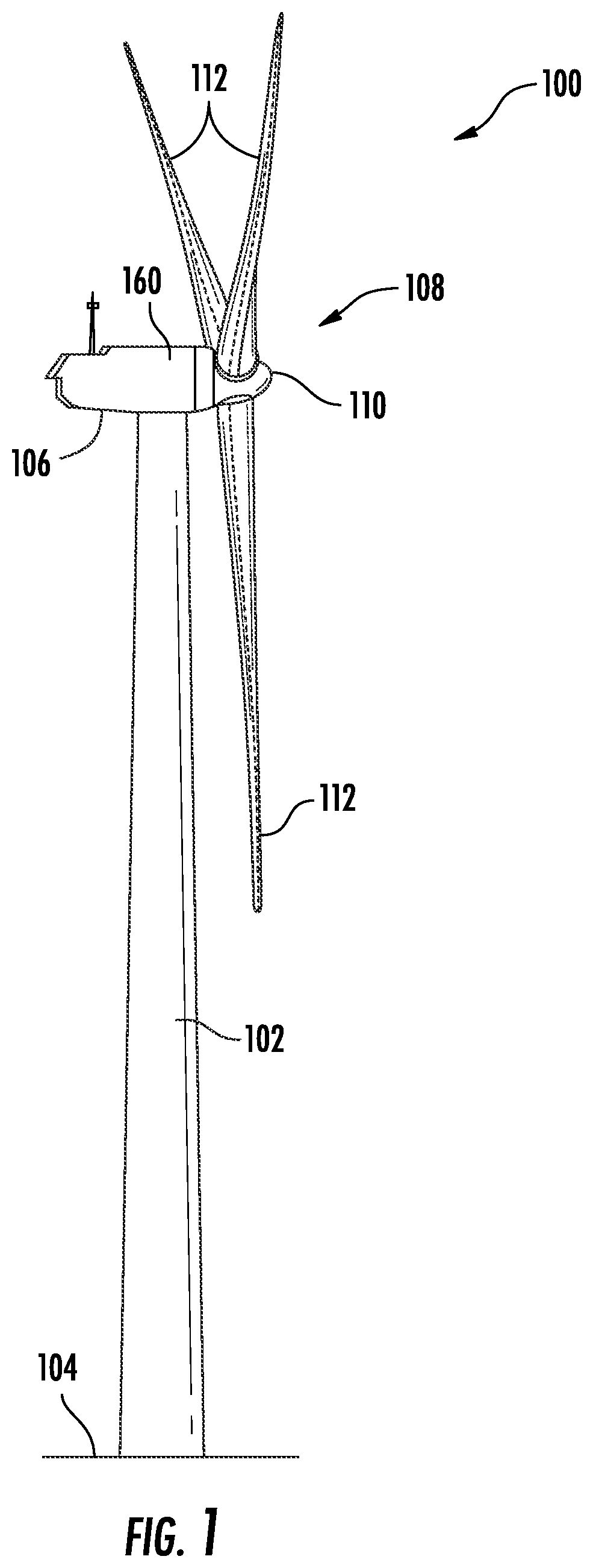
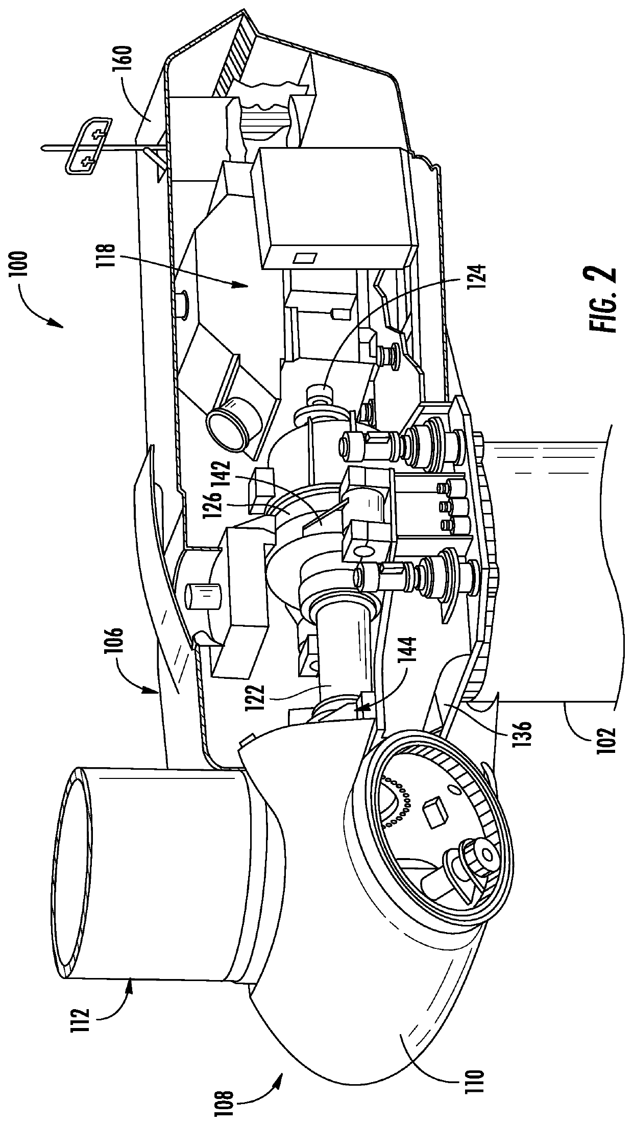
FIELD[0001]The present disclosure relates in general to wind turbines, and more particularly to a mounting system and method for coupling a hub to a main shaft of the wind turbine.BACKGROUND[0002]Wind power is considered one of the cleanest, most environmentally friendly energy sources presently available, and wind turbines have gained increased attention in this regard. A modern wind turbine typically includes a tower, a generator, a gearbox, a nacelle, and a rotor having a rotatable hub with one or more rotor blades secured thereto. The rotor may also be mechanically coupled to a main shaft that drives the gearbox. The gearbox then drives the generator. The main shaft, the gearbox, and the generator are mounted on a bedplate support frame located within the nacelle. The one or more rotor blades capture kinetic energy of wind using known airfoil principles. The rotor blades transmit the kinetic energy in the form of rotational energy so as to turn a shaft coupling the rotor blades ...

Claims


Application Information

Patent Timeline
Patent Type & Authority Applications(United States)
IPC IPC(8): F16B21/16F03D80/80F03D80/70H02K7/18F03D13/20F03D13/10
CPCF16B21/16F03D80/88F03D13/10H02K7/1838F03D13/20F03D80/70F03D1/065F05B2230/60F05B2230/604Y02E10/728Y02E10/72
Inventor MOORE, BRADLEY GRAHAMSAMAL, RAKESHPAWAR, HEMANT BHIMRAOBIRKENSTOCK, JOSEPH EDWARD
Owner GENERAL ELECTRIC CO
Why Eureka
Try Eureka