Eureka AIR delivers breakthrough ideas for toughest innovation challenges, trusted by R&D personnel around the world.

Transmitter with compensation of vco pulling

Active Publication Date: 2021-07-15
SHENZHEN GOODIX TECH CO LTD
View PDF8 Cites 0 Cited by
  • Summary
  • Abstract
  • Description
  • Claims
  • Application Information

AI Technical Summary

Benefits of technology

The patent is about a transmitter circuit that includes a frequency circuit, a power amplifier, and a programmable delay circuit. This circuit is unique because it allows for control over the delay between the frequency signal and the power amplifier's drive signal. The programmable delay circuit is programmed to pass a calibration test and can be adjusted based on the programming value. The technical effect of this invention is that it provides greater flexibility and control over the timing of the signal transmission process, which can improve the overall efficiency and reliability of the transmitter.

Problems solved by technology

The coupled signal disturbs the output of the PLL, such that the frequency output of the PLL is undesirably shifted from its intended target.

Method used


Image

  • Transmitter with compensation of vco pulling
  • Transmitter with compensation of vco pulling

Examples


Embodiment Construction

[0008]Particular embodiments of the invention are illustrated herein in conjunction with the drawings.

[0009]Various details are set forth herein as they relate to certain embodiments. However, the invention can also be implemented in ways which are different from those described herein. Modifications can be made to the discussed embodiments by those skilled in the art without departing from the invention. Therefore, the invention is not limited to particular embodiments disclosed herein.

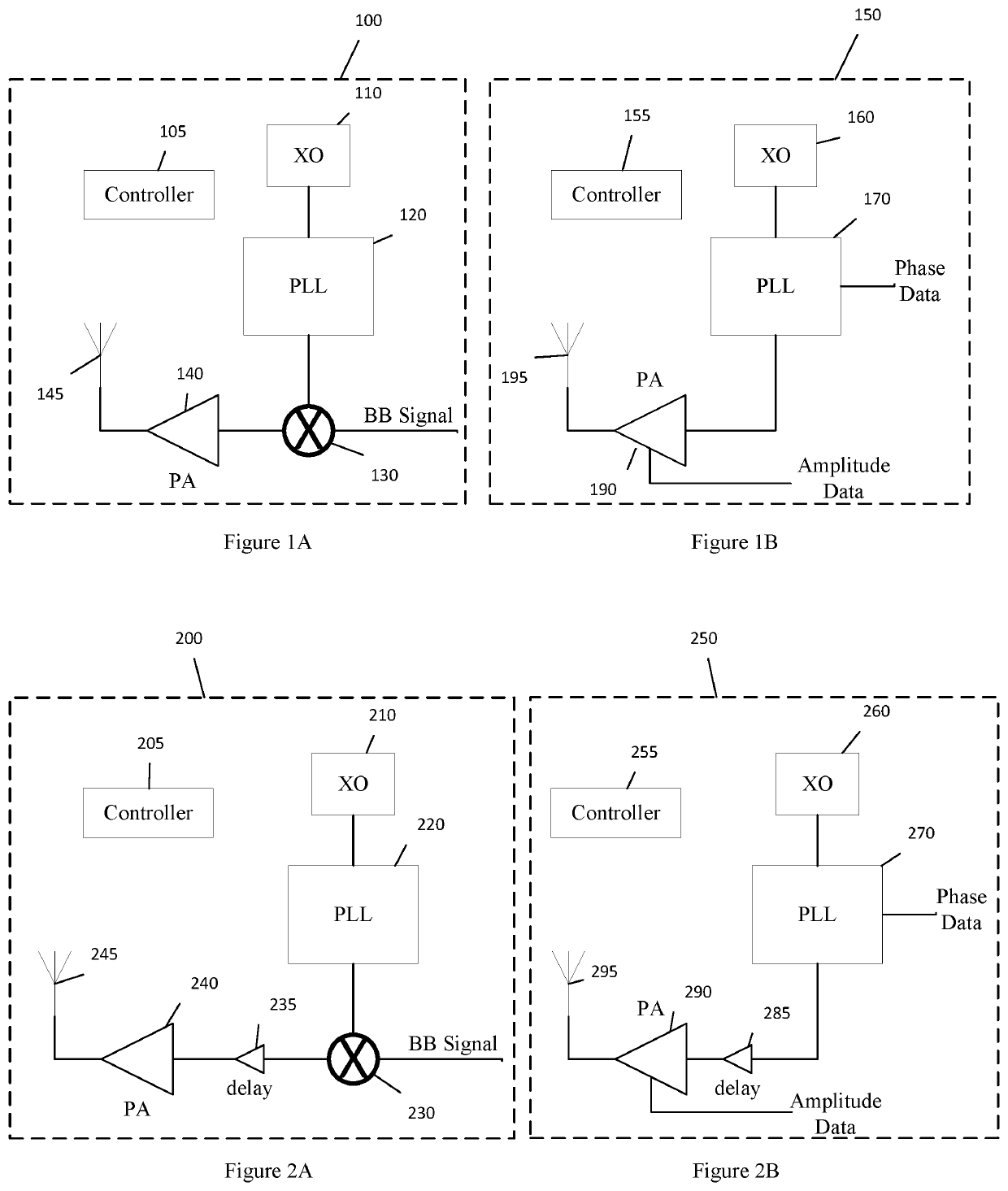
[0010]FIG. 1A is a schematic diagram of a linear or direct conversion transmitter circuit 100 according to an embodiment.

[0011]Linear conversion transmitter circuit 100 includes controller 105, crystal oscillator (XO) circuit 110, phase locked loop circuit 120, mixer 130, power amplifier 140, and antenna 145.

[0012]Crystal oscillator circuit 110 generates a reference frequency which is used by phase locked loop circuit 120 to generate an RF transmission frequency signal. Mixer 130 modulates the RF tra...


PUM


Abstract

A transmitter circuit is disclosed. The transmitter circuit includes a frequency circuit configured to generate a frequency signal, a power amplifier configured to drive an antenna with a drive signal according to the frequency signal, and a programmable delay circuit configured to controllably extend a propagation delay between the frequency signal generated by the frequency circuit and the drive signal of the power amplifier. The programmable delay circuit is programmed with a programming value which causes the transmitter circuit to pass a calibration test.

Description

FIELD OF THE INVENTION[0001]The present application generally pertains to transmitter circuits, and more particularly to transmitter circuits which have low frequency shift induced as a result of the power amplifier.BACKGROUND OF THE INVENTION[0002]Transmitter circuits frequently have a phase locked loop (PLL) circuit which generates a signal which is modulated with an information carrying signal and transmitted with an antenna driven by a power amplifier. The power amplifier tends to generate a signal which is coupled to the PLL. The coupled signal disturbs the output of the PLL, such that the frequency output of the PLL is undesirably shifted from its intended target. This phenomenon may be called pulling or VCO pulling.BRIEF SUMMARY OF THE INVENTION[0003]One inventive aspect is a transmitter circuit. The transmitter circuit includes a frequency circuit configured to generate a frequency signal, a power amplifier configured to drive an antenna with a drive signal according to the ...

Claims


Application Information

Patent Timeline
IPC IPC(8): H04B1/04H04B17/11H03C3/09H03F3/24
CPCH04B1/04H04B17/11H04B2001/0408H03F3/24H04B2001/0491H03C3/0983H03C2200/0041H03C5/00H04B17/12H04B17/13
Inventor EMIRA, AHMEDHUSSIEN, FAISAIBABAKRPUR NALOUSI, ESMAIL
Owner SHENZHEN GOODIX TECH CO LTD
Why Eureka
Eureka Blog
Learn More