

Part for a turbomachine centrifugal breather having a filtering mesh
- Summary
- Abstract
- Description
- Claims
- Application Information
AI Technical Summary
Benefits of technology
Problems solved by technology
Method used
Image

Examples
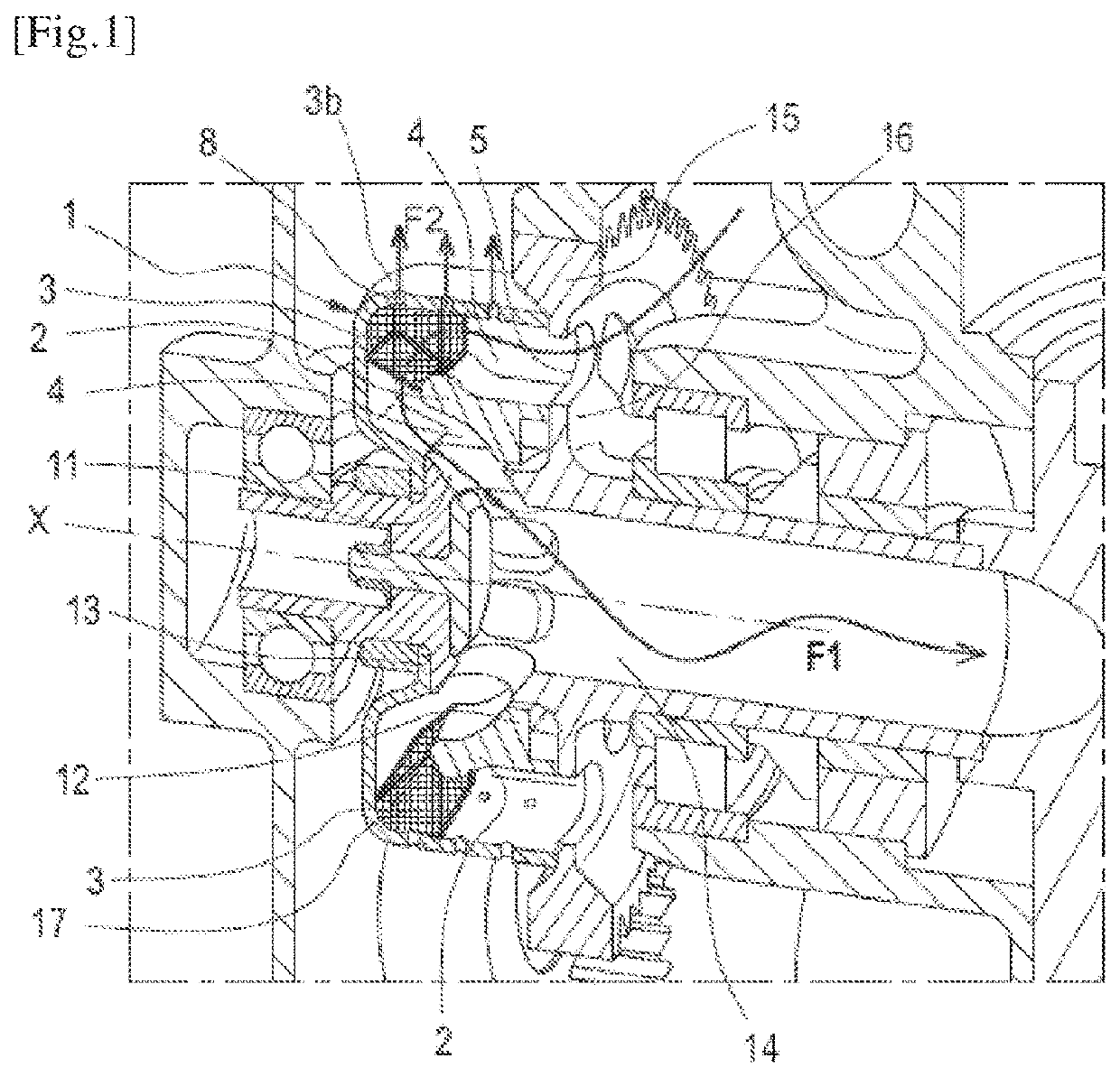
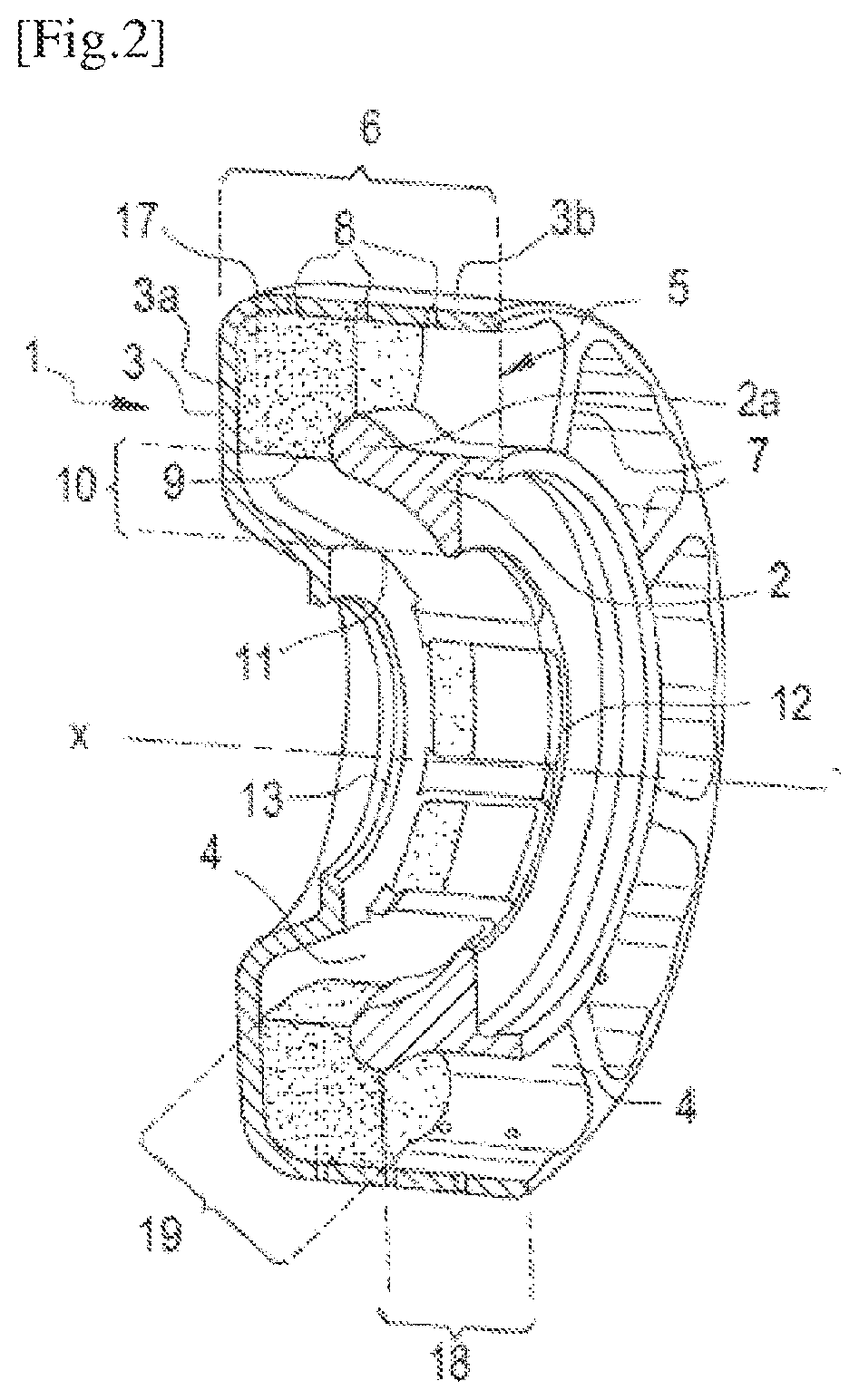
first embodiment
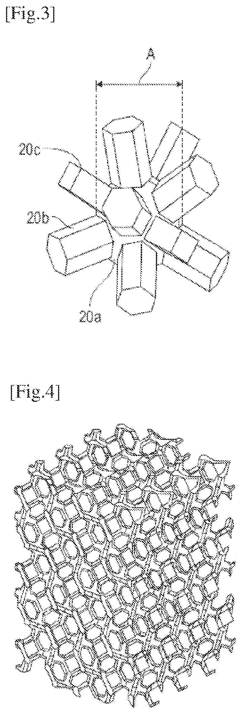
[0054] with reference to FIG. 3, the voids form a pattern in which a central sphere 20a is connected to a first series of eight cylindrical bars 20b of hexagonal cross-section, with octagonal symmetry. Furthermore, between four bars 20b of the first series, a cylindrical bar 20c of square section is connected to said sphere 20a, forming a second series of six perpendicular bars. The diameter A of the central sphere 20a is typically about 2.5 mm. The pattern repeats spatially in the three spatial directions defined by the bars 20c of the second series which connect the central sphere 20a to six other void spheres in the network of the mesh. The bars 20b of the first series connect the central sphere 20a to the eight other central spheres surrounding it diagonally in the network of the mesh. The length of the bars 20b and 20c is adjusted to obtain a very airy mesh, typically with a porosity of 90%. FIG. 4 illustrates the type of material network obtained for such a mesh. It can be see...
second embodiment
[0055] with reference to FIG. 5, the voids form a pattern where a central sphere 21a, with a diameter A between approximately 2 mm and 2.2 mm, intersects with a series of four spheres 21b of smaller diameter, in a cubic network symmetry. The pattern of void volumes, repeated in the three directions of space, gives in addition a material network for the mesh as shown in FIG. 6. With this organisation, the porosity of the mesh is rather of the order of 85%. Here again, we see that a fluid passing from a central sphere 21b to another following one of the diagonals of the cubic network, is confronted with constrictions or pinches when passing from the central sphere 21a to an intermediate sphere 21b.
third embodiment
[0056] with reference to FIG. 7, the voids form a pattern where a central sphere 22a, is connected to a series of other spheres 22b by bars 22c of cylindrical section, following the diagonals of a cubic network. Typically the diameter A of a sphere 22a or 22b in this network is of the order of 2.5 mm. The length and cross-section of the bars is adjusted here to obtain a porosity of about 77%. FIG. 8 illustrates the type of material network that can be obtained for such a mesh. Here again, it can be seen that the passage of fluid in the different directions is pinched or constricted between the bars 22c and spheres 22a or 22b.
[0057]These first three embodiments combine high porosity, allowing a mixture loaded with droplets to pass through the mesh with a large contact surface between the material and the void, which can facilitate the capture of the droplets by the mesh.
PUM
| Property | Measurement | Unit |
|---|---|---|
| Length | aaaaa | aaaaa |
| Length | aaaaa | aaaaa |
| Time | aaaaa | aaaaa |
Abstract
Description
Claims
Application Information