
System and Methods for Use With Electronically Steerable Antennas for Wireless Communications

an electronic steerable array and wireless communication technology, applied in the field of wireless communications antennas, can solve the problems of reducing so as to reduce the beam width and increase the power consumption of antennas.

Pending Publication Date: 2021-07-29
GILAT SATELLITE NETWORKS
View PDF32 Cites 3 Cited by
  • Summary
  • Abstract
  • Description
  • Claims
  • Application Information

AI Technical Summary

Benefits of technology

The patent text discusses the importance of antennas with a narrow beam-width for better focusing of electromagnetic energy in a particular direction. It also mentions that the beam-width of an antenna can be related to its aperture dimension and can be symmetrical or non-symmetrical. To compensate for scan losses and narrow the beam width, multiple antenna elements can be used. However, this may increase power consumption. The technical effects of the patent text include improving antenna performance with a narrow beam-width and addressing the issue of power consumption.

Problems solved by technology

It has been found that the planar phased array antennas may be susceptible to “scan loss,” which may account for a drop in antenna directivity versus scanning angle measured from the normal to antenna plane (boresight direction) to a beam direction.
It has also been found that phased array antennas may be susceptible to a broadening of antenna beam-width at large scan angles, which, in a receiving (Rx) mode of operation, may lead to adjacent satellite interferences (ASI) (e.g., from neighboring satellites at geostationary orbits).
In a transmitting (Tx) mode of operation, the phased array antennas may be susceptible to generating interferences to adjacent satellites and therefore exceed government regulations for equivalent isotropically radiated power (EIRP) Spectral Density (ESD).
For example, when an antenna mounted on a moving platform, e.g., an aircraft, communicates with geostationary earth orbit (GEO) satellites at low elevation angles (which may be associated with large angle beam scanning), the aircraft flight path and aircraft maneuvers may cause the beam to skew to some extent that may introduce interference to adjacent satellites.
Radiating patterns of these antennas may not comply with the government regulations, such as European Telecommunications Standards Institute (ETSI) and / or U.S. Federal Communications Commission (FCC) off-axis and / or on-axis EIRP Spectral Density regulations.

Method used


Image

  • System and Methods for Use With Electronically Steerable Antennas for Wireless Communications
  • System and Methods for Use With Electronically Steerable Antennas for Wireless Communications
  • System and Methods for Use With Electronically Steerable Antennas for Wireless Communications

Examples


Embodiment Construction

[0023]Wireless communications utilize antennas to transmit and receive signals between different devices. For example, a satellite communication system for commercial, non-commercial, and / or business applications (e.g., aviation) may comprise antennas mounted on a remote station such as a fixed or mobile device (e.g., an aircraft), a satellite, and / or a ground earth station (GES) (e.g., a Hub station). The antennas may provide for reception and transmission of the electromagnetic signals communicated between, for example, the remote station(s) and / or other remote station(s) and / or Hub station(s). A variety of remote antenna types may be used including, but not limited to: steered flat panel antennas (e.g., mechanically steerable passive arrays and / or electronically steerable active arrays), reflectors and / or reflector arrays, hybrid steering antennas (combining mechanical steering with electronic steering), and electronic steerable antennas such as phased array antennas (PAA) which ...


PUM


Abstract

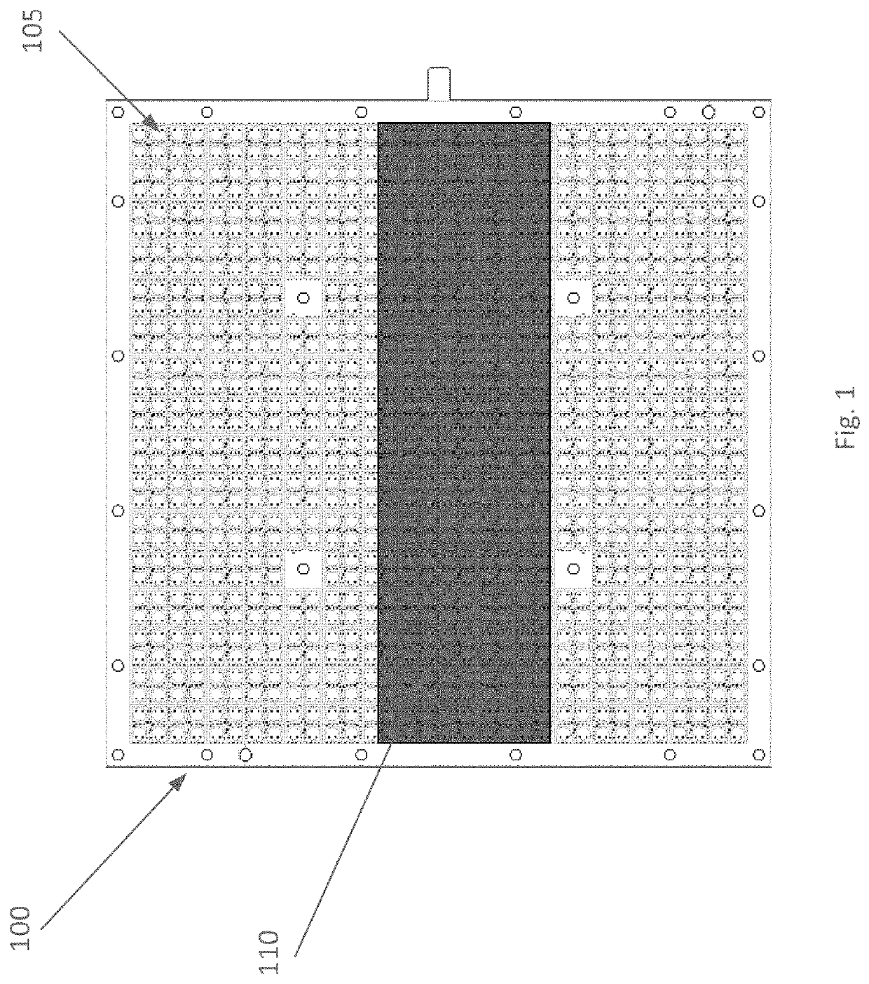
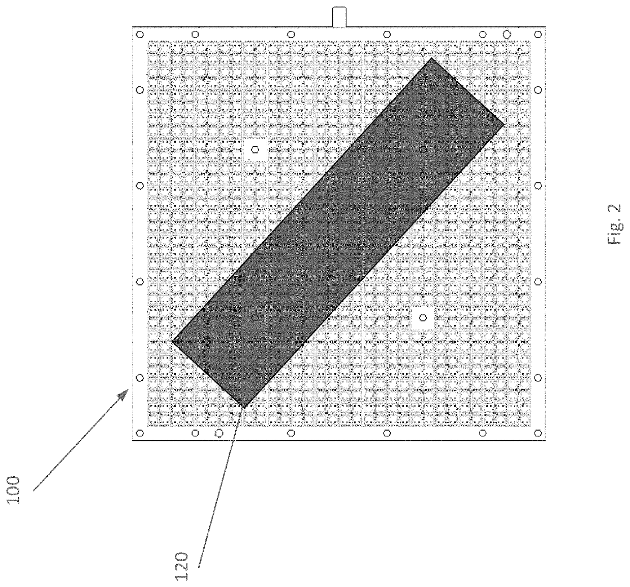
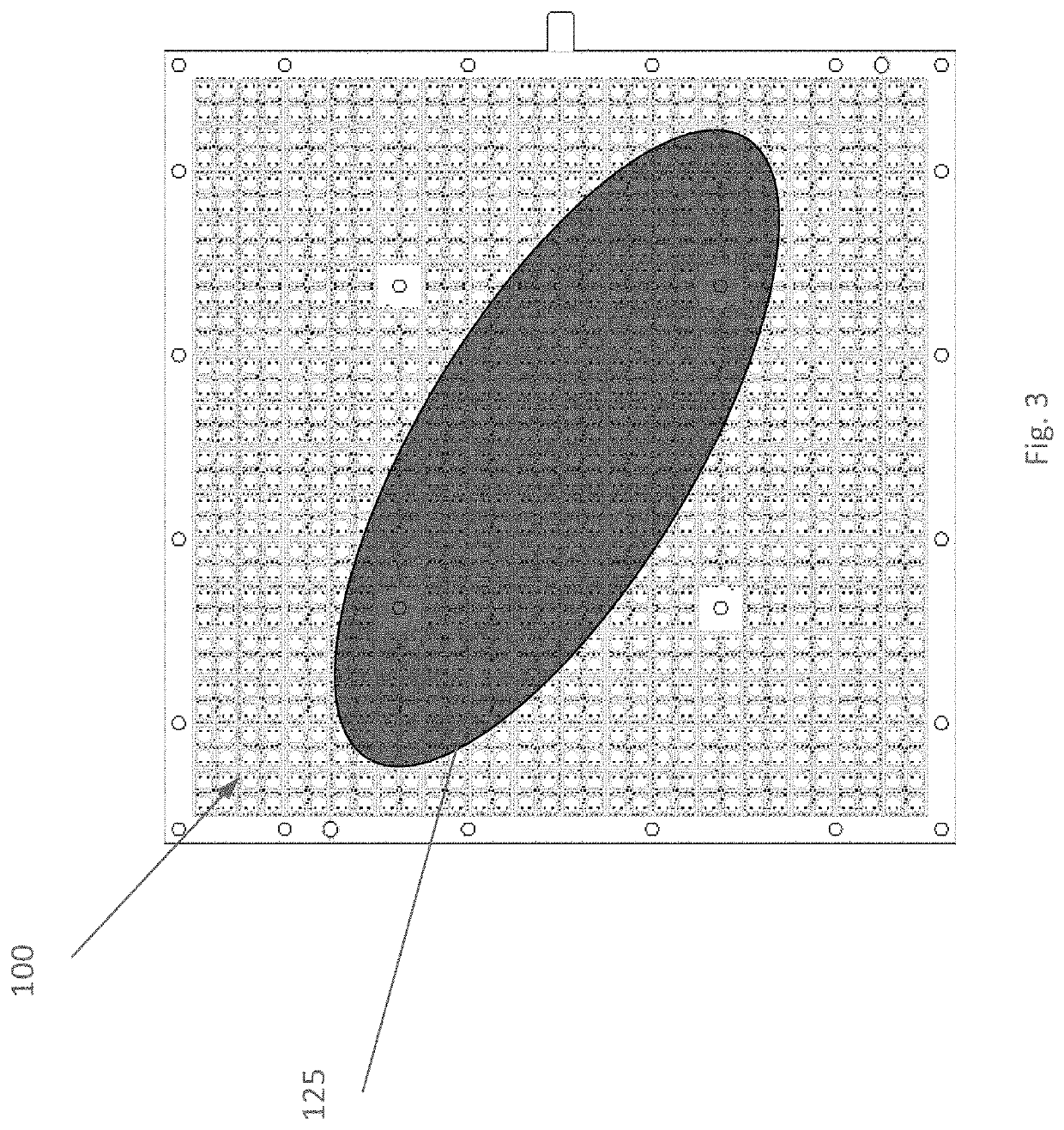
Examples disclosed herein describe an antenna with antenna elements that may be selectively activated and deactivated to define active apertures. The active apertures may be of different shapes and sizes. An antenna may include one active aperture or multiple active apertures at a point in time. These one or more active apertures may be reconfigured, e.g., by deactivating the active antenna elements and activating other antenna elements.

Description

CROSS-REFERENCE TO RELATED APPLICATIONS[0001]This application claims priority to U.S. Provisional Application No. 62 / 965,358, entitled “Electrically Steerable Antennas for Wireless Communications,” filed Jan. 24, 2020 and to U.S. Provisional Application No. 62 / 968,471, entitled “System and Method for Use with Electronically Steerable Antennas for Wireless Communications,” filed Jan. 31, 2020. Each of these applications is incorporated herein by reference in its entirety.TECHNICAL FIELD[0002]Aspects of the disclosure pertain to antennas for wireless communications. Some aspects pertain to electronically steerable array (ESA) antennas for wireless communications.BACKGROUND[0003]Wireless communication systems, including systems for communication via satellites, are being used for a variety of civil and military applications, including aviation, maritime, and land-mobility. Antennas may be used to transmit and receive wireless signals between various distant devices. In some cases, the ...

Claims


Application Information

Patent Timeline
Patent Type & Authority Applications(United States)
IPC IPC(8): H01Q3/36H04W16/28H01Q3/28
CPCH01Q3/36H01Q3/28H04W16/28H01Q21/0006H01Q3/247
Inventor STOLERU, RONENPESHLOV, VESSELIN
Owner GILAT SATELLITE NETWORKS
Learn More