Rotating electric machine

a technology of rotating electric machines and rotating parts, which is applied in the direction of rotating parts of magnetic circuits, magnetic circuits characterised by magnetic materials, and magnetic circuits. it can solve the problems of limited use practicability of coreless or toothless stators

Pending Publication Date: 2021-07-29
DENSO CORP
View PDF0 Cites 13 Cited by
  • Summary
  • Abstract
  • Description
  • Claims
  • Application Information

AI Technical Summary

Benefits of technology

[0042]In contrast, with the configuration of the above-described rotating electric machine according to the present disclosure, it becomes possible to increase, by the soft-magnetic member provided on at least part of the surface of the coil end part, the leakage inductance of the stator coil while keeping a coil side part of the stator coil, which does not protrude from the stator coil holder, from affecting the main characteristics. That is, though the main inductance remains unchanged, the total inductance of the stator coil is increased due to the increase in the leakage inductance. Consequently, it becomes possible to increase the first-order lag element of electric current supplied to the stator coil. As a result, it becomes possible to suppress fluctuations of the electric current to be small even with PWM control performed at a conventional switching frequency of 10 kHz or lower. Accordingly, compared to a conventional rotating electric machine, it becomes possible to more stably perform the electric current control of the stator coil with the same controller capability.

Problems solved by technology

Moreover, the practical use of the coreless or toothless stators has conventionally been limited to small-scale brushed DC motors for model applications and the like.

Method used


Image

  • Rotating electric machine
  • Rotating electric machine
  • Rotating electric machine

Examples


first embodiment

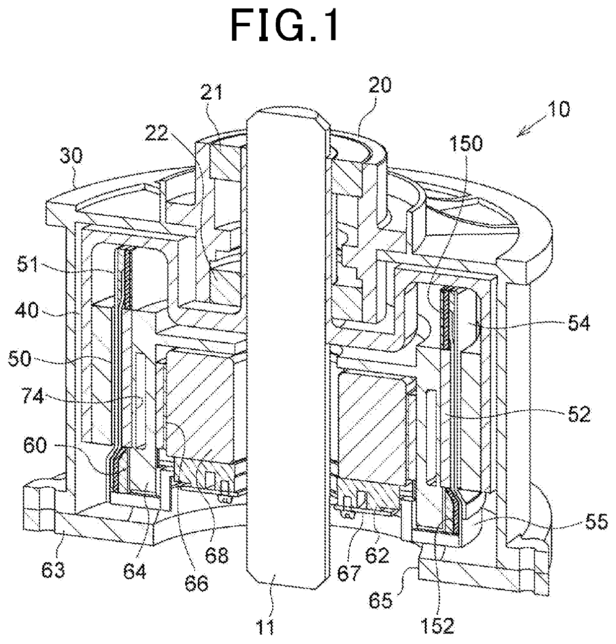
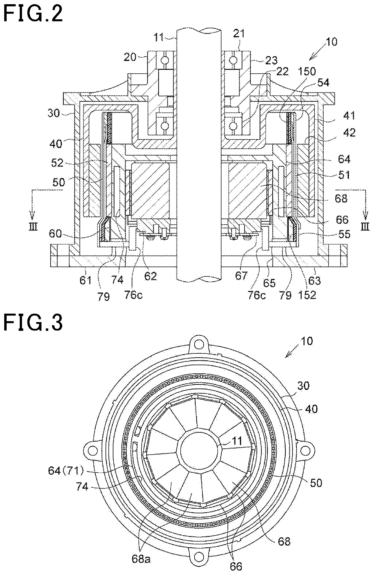
[0045]The rotating electric machine 10 according to the present embodiment is a synchronous multi-phase AC motor with an outer rotor structure (i.e., an outer rotating structure). The outline of the rotating electric machine 10 is illustrated in FIGS. 1 to 5.

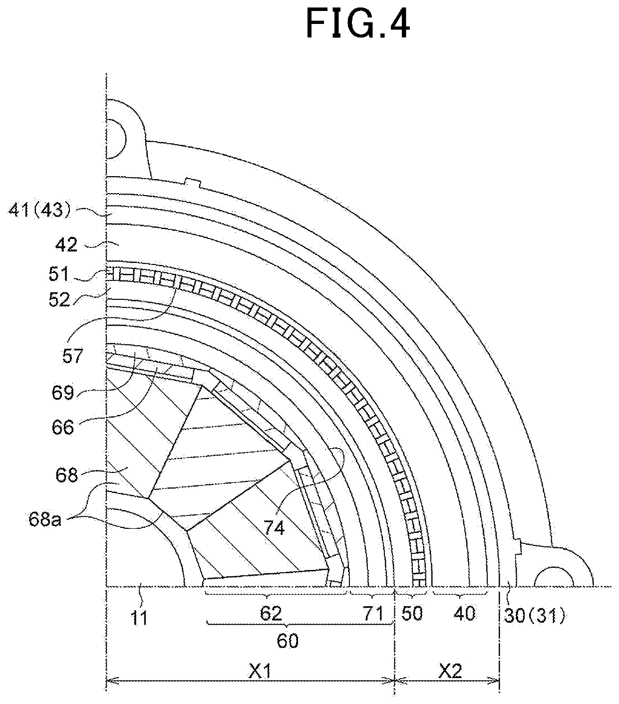
[0046]FIG. 1 is a perspective longitudinal cross-sectional view of the rotating electric machine 10. FIG. 2 is a longitudinal cross-sectional view along a rotating shaft 11 of the rotating electric machine 10. FIG. 3 is a transverse cross-sectional view (i.e., cross-sectional view taken along the line III-III in FIG. 2) of the rotating electric machine 10 perpendicular to the rotating shaft 11. FIG. 4 is an enlarged cross-sectional view of part of FIG. 3. FIG. 5 is an exploded view of the rotating electric machine 10. In addition, it should be noted that in FIG. 3, for the sake of simplicity, hatching lines designating cross sections of components of the rotating electric machine 10 except for the rotating shaft 11 are omitted.

[...

second embodiment

[0167]In the present embodiment, the polar anisotropic structure of the magnet unit 42 of the rotor 40 is modified in comparison with that described in the first embodiment. The polar anisotropic structure according to the present embodiment will be described in detail hereinafter.

[0168]As shown in FIGS. 22 and 23, in the present embodiment, the magnet unit 42 is configured with a magnet array called a Halbach array. Specifically, the magnet unit 42 includes first magnets 131 each having its magnetization direction (or the orientation of the magnetic pole thereof) coincident with a radial direction and second magnets 132 each having its magnetization direction (or the orientation of the magnetic pole thereof) coincident with the circumferential direction. The first magnets 131 are arranged at predetermined intervals in the circumferential direction. Each of the second magnets 132 is arranged between one circumferentially-adjacent pair of the first magnets 131. In addition, the first...

first modification

[0218]FIG. 29 shows part of a soft-magnetic member 150 according to a first modification.

[0219]In this modification, the soft-magnetic member 150 is obtained by press-forming a long band-shaped sheet 153 into a hollow cylindrical shape; the sheet 153 is made of a soft-magnetic material (e.g., magnetic stainless steel). The soft-magnetic member 150 is mounted on the inner circumferential surface of the coil end part 54.

[0220]Moreover, on an outer circumferential surface of the soft-magnetic member 150, there are formed a plurality of protrusions 150A. The protrusions 150A extend along the turn portions 84 of the stator coil 51 obliquely with respect to the axial direction and are aligned with each other in the circumferential direction. The soft-magnetic member 150 is mounted on the inner circumferential surface of the coil end part 54 with the protrusions 150A fitted respectively into the gaps between the electrical conductors 82 in the coil end part 54. Consequently, the soft-magne...


PUM


Abstract

A rotating electric machine includes a rotor and a stator. The rotor includes a magnet section constituted of permanent magnets. The stator is arranged coaxially with the rotor and includes a stator coil and a stator coil holder. The stator coil is formed of electrical conductors arranged in a circumferential direction of the stator. The stator coil holder is configured to hold the stator coil. In the stator, there are provided inter-conductor members between the electrical conductors in the circumferential direction or no inter-conductor members are provided between the electrical conductors in the circumferential direction. Moreover, the inter-conductor members are formed of a magnetic material satisfying a predetermined relationship or formed of a nonmagnetic material. The stator coil has a coil end part protruding from an axial end of the stator coil holder. A soft-magnetic member is provided on at least part of a surface of the coil end part.

Description

CROSS-REFERENCE TO RELATED APPLICATIONS[0001]The present application is a continuation application of International Application No. PCT / JP2019 / 034224 filed on Aug. 30, 2019, which is based on and claims priority from Japanese Patent Application No. 2018-191111 filed on Oct. 9, 2018. The entire contents of these applications are hereby incorporated by reference into the present application.BACKGROUND1. Technical Field[0002]The present disclosure relates to rotating electric machines.2. Description of Related Art[0003]Coreless or toothless stators for motors have been proposed to reduce the weights and improve the efficiencies of the motors (see, for example, Japanese Patent Application Publication No. JP 2012-175755 A). In these stators, no teeth are provided between electrical conductors forming a stator coil. Moreover, the practical use of the coreless or toothless stators has conventionally been limited to small-scale brushed DC motors for model applications and the like.SUMMARY[0...

Claims


Application Information

Patent Timeline
Patent Type & Authority Applications(United States)
IPC IPC(8): H02K1/18H02K3/28H02K1/27H02K1/02
CPCH02K1/187H02K3/28H02K2213/03H02K1/02H02K1/2786H02K3/47H02K11/33H02K21/222H02K1/2791
Inventor TANIGUCHI, MAKOTOTAKAHASHI, YUKI
Owner DENSO CORP
Why Eureka
Try Eureka