Machining tool and workpiece measurement method
- Summary
- Abstract
- Description
- Claims
- Application Information
AI Technical Summary
Benefits of technology
Problems solved by technology
Method used
Image

Examples
first embodiment
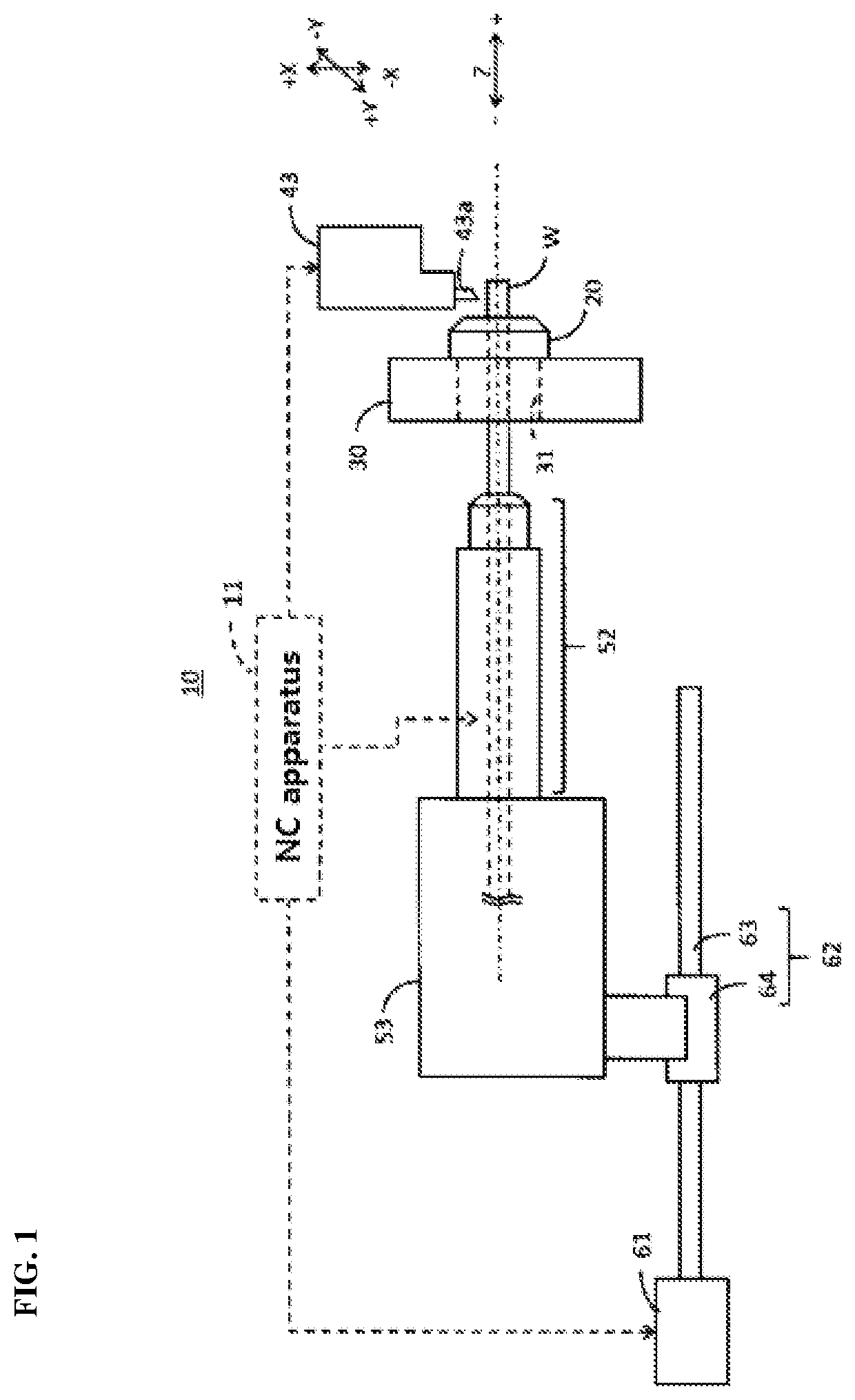
[0041]FIG. 4 is a drawing for explaining the displacement sensor 70 of the first embodiment. The drawing is a sectional view (vertical to the Y-axis direction) of the GB 20 attached to the through-hole 31 of the GB supporting unit 30. The GB 20 is not hatched only for visibility.
[0042]The GB 20 may comprise a cylindrical non-rotatable section 21 and a rotatable section (23, 24) inside the non-rotatable section 21. The rotatable section (23, 24) holding the workpiece W may be rotatable on the Z-axis in synchronization with the spindle 52. A bearing 22 may be disposed between the non-rotatable section 21 and the rotatable section (23, 24). The section inside the bearing 22, which is the rotatable section (23, 24), may be rotatable. The rotatable section (23, 24) may be rotatable in synchronization with the spindle 52 by receiving the power of the spindle motor 51 (FIG. 2). Alternatively, the rotatable section (23, 24) may be rotatable in synchronization with the spindle 52 by recei...
second embodiment
[0051]FIG. 6 is a drawing for explaining the displacement sensor 70 of the second embodiment. The drawing is a sectional view (vertical to the Y-axis direction) of the spindle 52 inserted in the through-hole 31 of the GB supporting unit 30. The spindle 52 is not hatched only for visibility. The GB 20 shown in FIG. 1 and FIG. 4 is removed from the GB supporting unit 30. The headstock 53 may be moved to the front side until the spindle 52 is inserted into the through-hole 31 of the GB supporting unit 30 to be supported by the GB supporting unit 30. The inner wall of the GB supporting unit 30 may be of a shape capable of stably supporting the inserted spindle 52.
[0052]When the inserted spindle 52 is positioned with respect to the GB supporting unit 30, part of the front end of the spindle 52 may be protruded from the GB supporting unit 30 to the front side. The workpiece W held by the spindle 52 supported by the GB supporting unit 30 may be protruded from the spindle 52 to the front...
PUM
| Property | Measurement | Unit |
|---|---|---|
| Temperature | aaaaa | aaaaa |
| Diameter | aaaaa | aaaaa |
Abstract
Description
Claims
Application Information
 - R&D
- Intellectual Property
- Life Sciences
- Materials
- Tech Scout
- Unparalleled Data Quality
- Higher Quality Content
- 60% Fewer Hallucinations
Browse by: Latest US Patents, China's latest patents, Technical Efficacy Thesaurus, Application Domain, Technology Topic, Popular Technical Reports.
© 2025 PatSnap. All rights reserved.Legal|Privacy policy|Modern Slavery Act Transparency Statement|Sitemap|About US| Contact US: help@patsnap.com