Conical scan weather radar

a scanning radar and scan technology, applied in computing, instruments, generating/distributing signals, etc., can solve the problems of large size and weight of subsystems, large power consumption, and inability to embed instruments, and achieve the effect of reducing the swapping of systems, simplifying calibration, and reducing the swapping of sdrrs

Pending Publication Date: 2021-08-05
REMOTE SENSING SOLUTIONS INC
View PDF0 Cites 0 Cited by
  • Summary
  • Abstract
  • Description
  • Claims
  • Application Information

AI Technical Summary

Benefits of technology

[0012]To further reduce the SWaP of the system, the present disclosure employs a unique simultaneous frequency diversity approach in the SDRr. In this arrangement a single SDRr transmit / receive channel is employed to support multiple antenna beams simultaneously. Through a wide bandwidth arbitrary waveform generator (i.e. digital to analog converter, DAC), simultaneous waveforms may be generated that are separated in frequency. This signal channel output is then separated, in this case into four channels either in the IF or RF transmit section of the radar transmitter (depends on final transmit frequency and optimal radar frequency plan). After being separated, each signal can be sent through the final transmit path to the antenna feed for its beam. On reception of the receive signals from each antenna beam, the receive signals can be amplified and combined either in the RF or IF section of the radar system and sent to a signal digital receiver channel (i.e., ADC). Using sub channels and digital bandpass filtering, the return from each antenna beam can be separated and processed. This approach allows for a single ADC and DAC to be used thus reducing the SWaP of the SDRr, and also simplifies the calibration through using common waveform generation and processing hardware for all antenna beams.
[0013]In the disclosure of the present invention, wide swath coverage and high spatial resolution are provided through azimuth rotation at constant incidence which in turn allows high sensitivity pencil beam geometry. Further, the use of constant scan incidence simplifies calibration and geophysical retrievals that facilitates constant measurement error across the entire swath.
[0014]The use of a fixed beam allows optimization of the sidelobe (SL) pattern to suppress surface return in lower boundary scan layer, while dual beam sampling can eliminate SL contamination. Further this arrangement provides multiple looks (fore and aft) for improved measurement precision and retrievals.
[0015]With electronic scanning the beam can also be held in placed and stepped to the next pixel which will improve the spatial resolution. In contrast mechanical scanning will sweep the beam which means it smears it. Electronic scanning also allows for motion (time) to be compensated for so the transmit beam and receive beam are aligned.

Problems solved by technology

This results in a bulky subsystem that occupies significant size and weight and consumes considerable power (SWaP), and that cannot be embedded in the instrument itself.
These conventional sub-systems require custom firmware and software development, and require significant development, integration and testing.
These development activities take significant time and resources and are extremely costly.
Custom single board solutions can reduce SWaP but further increase development costs.
Additionally, custom solutions offer less flexibility for reconfiguration and limit future expansion.
This limits the use of the solutions in other systems, or even for different applications for the system it was originally designed for.

Method used


Image

  • Conical scan weather radar
  • Conical scan weather radar
  • Conical scan weather radar

Examples


Embodiment Construction

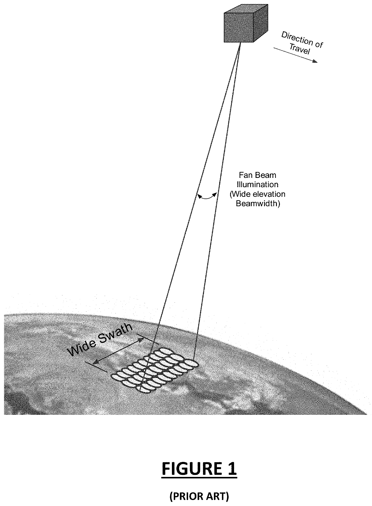
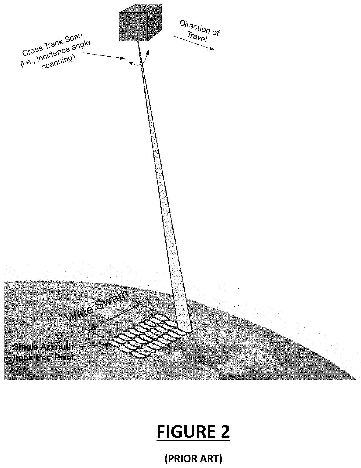
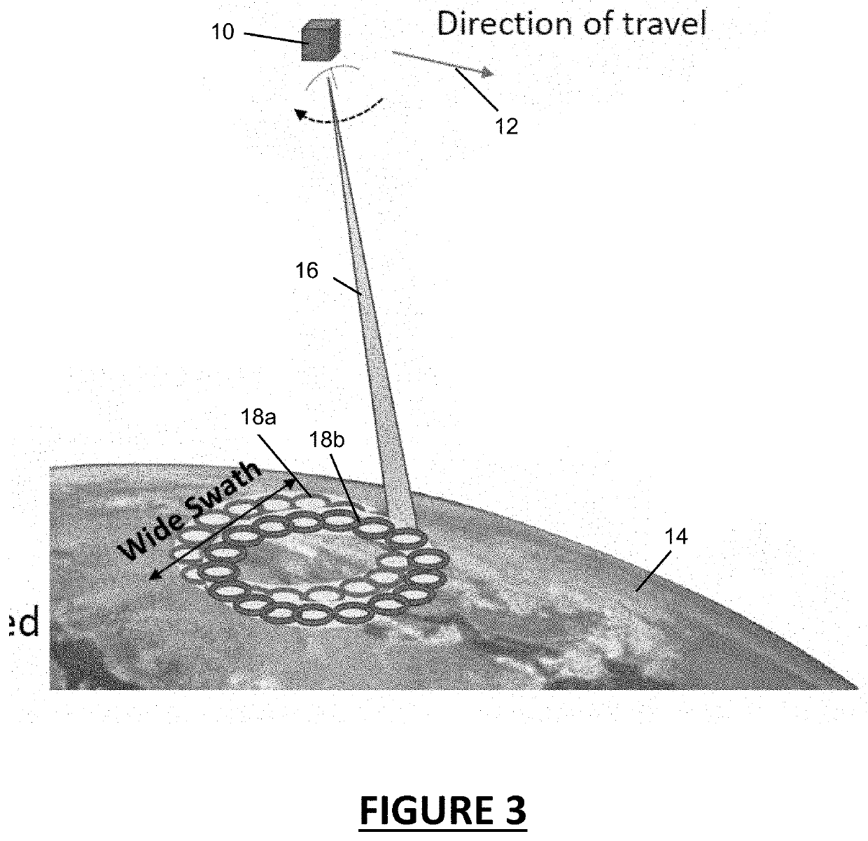
[0024]Now referring to the drawings, the new measurement approach that facilitates significantly smaller size, weight, and power (SWaP) spaceborne radar systems that can produce wide swath, high resolution observations is depicted in FIGS. 3-6. The disclosed system allows observations of multiple parameters, weather and Earth processes from space based and stratospheric platforms. This approach combines a multi-antenna beam conical scan geometry with a multi-mode reconfigurable software defined radar (SDRr) system.

[0025]As depicted in FIG. 3, a general schematic of an exemplary system and method in accordance with the disclosure is provided. A radar scanning satellite 10, is deployed in orbit having a travel direction 12 about the Earth 14. A beam array 16 is electronically swept over a wide swath scan pattern 18a. The satellite 10 radar scan platform is then indexed forward one step in the direction of travel 12 and the scan is repeated where the beam array 16 is swept over a wide ...


PUM


Abstract

A new measurement approach is disclosed that facilitates significantly smaller size, weight, and power (SWaP) spaceborne radar systems that can provide wide swath, high resolution observations. Multiple beams employed in the scan and the complex volume and/or surface backscatter signals of each beam is recorded. Each beam is electronically swept in azimuth where each beam is held at a constant incidence angle over the azimuth sector that covers the swath. Once the sweep is complete, the platform moves forward, by one along track pixel, and the sweep is repeated in order to provide continuous mapping of the volume and surface covered by the swath. Complex volume backscatter is recorded and mapped to each altitude layer to provide full mapping of the atmosphere.

Description

CROSS-REFERENCE TO RELATED APPLICATIONS[0001]This application is a continuation-in-part of U.S. application Ser. No. 17 / 163,640, filed Feb. 1, 2021, which is a continuation of U.S. application Ser. No. 15 / 939,562 filed Mar. 29, 2018, now U.S. Pat. No. 10,908,255, which claims the benefit of U.S. Provisional Patent Application No. 62479981 filed Mar. 31, 2017.[0002]This application is also related to and claims priority from earlier filed U.S. Provisional Patent Application No. 63 / 002,479, filed Mar. 31, 2020.BACKGROUND OF THE INVENTION[0003]The present disclosure relates to digital signal processing architectures that provide a new measurement approach in radar systems. More specifically, the present disclosure provides a new measurement approach that facilitates significantly smaller size, weight, and power (SWaP) spaceborne radar systems that can provide wide swath, high resolution observations.[0004]There is a need for improvement in the area of small satellite radar scanning too...

Claims


Application Information

Patent Timeline
Patent Type & Authority Applications(United States)
IPC IPC(8): G01S7/295G01S7/288G06F1/12G06F13/42G01S7/282G01S7/02G06F3/00
CPCG01S7/295G01S7/288G06F1/12G06F13/4221G01S2013/0245G01S7/02G06F3/00G06F2213/0026G01S7/282G01S13/422G01S13/9088G01S7/285G01S13/225G01S7/356
Inventor CARSWELL, JAMES R.
Owner REMOTE SENSING SOLUTIONS INC
Why Eureka
Try Eureka