Supercharge Your Innovation With Domain-Expert AI Agents!

Three Dimensional Printing Apparatus And A Method

a printing apparatus and three-dimensional technology, applied in the direction of additive manufacturing processes, manufacturing tools, applying layer means, etc., can solve the problems of difficult inability to have more than one material per layer, etc., to achieve convenient interchangeability, increase the effect of detail and accuracy

Inactive Publication Date: 2021-08-12
BURT MAXIMILIAN BARCLAY
View PDF0 Cites 1 Cited by
  • Summary
  • Abstract
  • Description
  • Claims
  • Application Information

AI Technical Summary

Benefits of technology

This approach enhances the accuracy and speed of 3D printing by allowing multiple materials to be printed simultaneously, reducing build time, and eliminating the need for secondary support structure removal, enabling the creation of complex shapes and hybrid materials with integrated properties.

Problems solved by technology

Disadvantages of the SLS method include the ability only to form a whole layer of the same material, the need for a roller to even out the laid powder and as a result, inaccuracies in the finished article.
Disadvantages of the FDM method lie in that it is difficult to have more than one material per layer and that support structure has to be created separately using a second filament and subsequently removed from the finished article.
A further disadvantage is that when the drops of melted plastic are dragged across the build plate a clean drag is unlikely to be obtained and therefore accuracy of the finished article is likely to be compromised.
A further disadvantage of this method is that it can only use light curable resins and cannot use other materials, for example, metals or ceramics.
This makes the process of creating a 3D object time consuming.

Method used


Image

  • Three Dimensional Printing Apparatus And A Method
  • Three Dimensional Printing Apparatus And A Method
  • Three Dimensional Printing Apparatus And A Method

Examples


Embodiment Construction

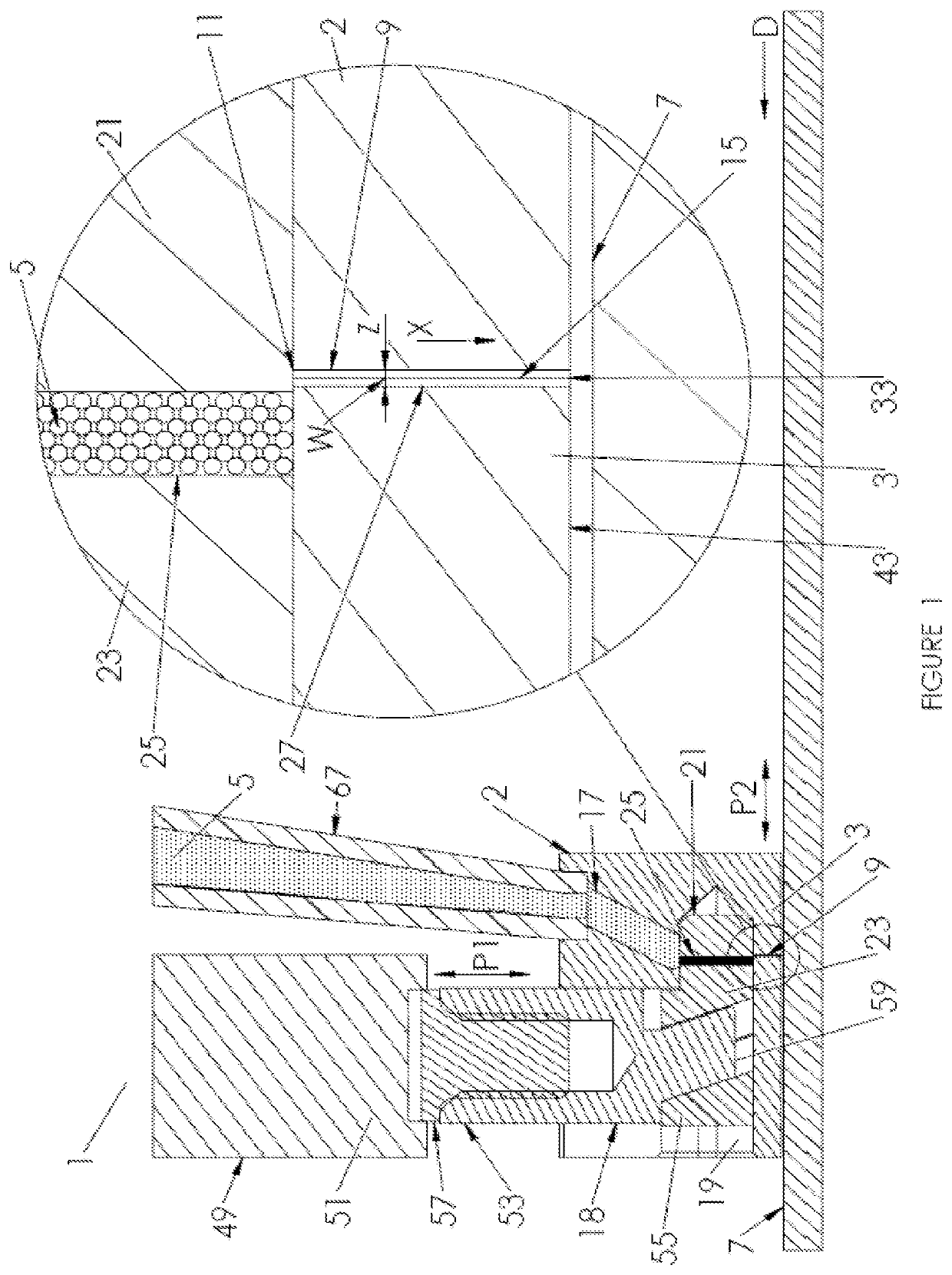
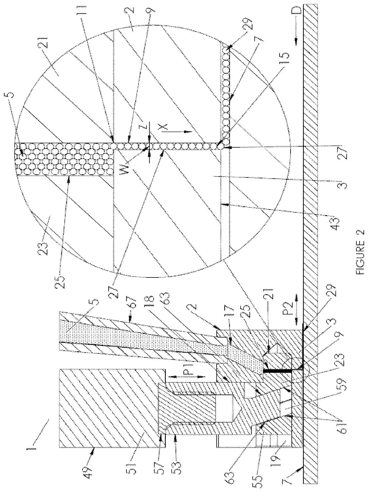
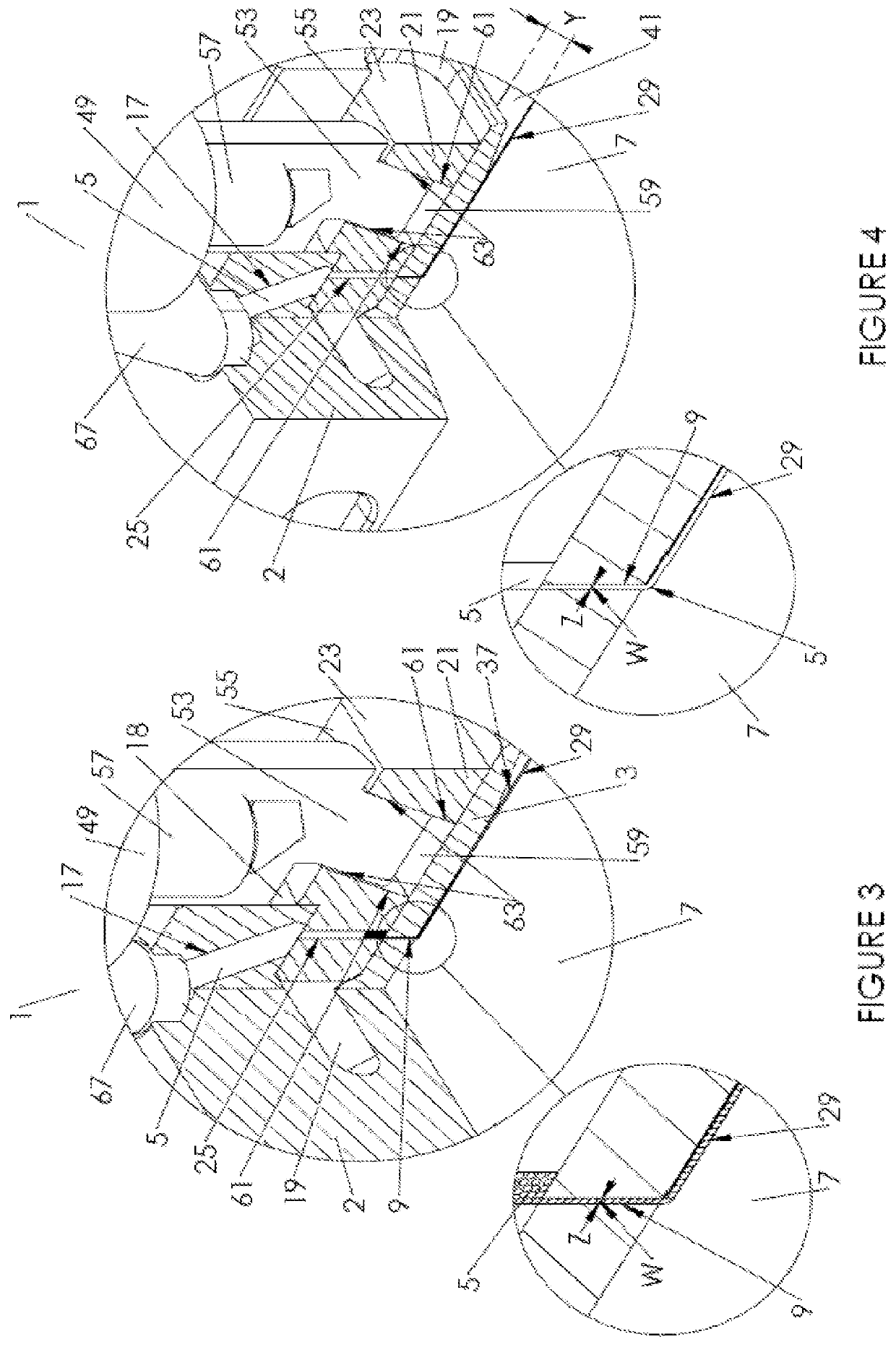
[0120]Referring to FIGS. 1 to 25, a three dimensional (3D) printing apparatus for forming three dimensional objects, a material dispensing unit therefor and a corresponding method of three dimensional printing will now be jointly described. The material dispensing unit of the invention is indicated generally using reference numerals 1 and 10 in the Figures. The 3D printing apparatus of the invention is indicated generally by reference numerals 100 and 200 in the Figures.

[0121]Referring initially to FIGS. 1 to 4, the material dispensing unit 1 for the three dimensional printing apparatus 100 comprises a housing 2 incorporating a nozzle 3 for depositing particulate material 5 on a build surface 7. It will be appreciated that in the present specification, for brevity, the term “build surface”, unless otherwise specified, includes an upper surface of a newly created layer onto which a subsequent layer is to be deposited as well as an upper surface of a build plate (to be described below...


PUM

PropertyMeasurementUnit
rotationaaaaaaaaaa
diameteraaaaaaaaaa
diameteraaaaaaaaaa

Abstract

A three dimensional printing apparatus (100; 200) is disclosed. The 3D printing apparatus comprises a primary and a secondary set of material dispensing units (1; 10) which each have a nozzle (3) for depositing particulate material (5; 220a, 220b; 224; 226) on a build surface (7), where the nozzle defines a through passage (9) for the material. The through passage has an inlet end (11) for receiving the material and an outlet end (15) for dispensing the material. A valve (21) is provided at least one of at, within or in fluid communication with the through passage for controlling flow of the material via the through passage, the valve being operable between open and closed positions. Flow of said material into the through passage is blocked when in the closed position and, when in the open position, flow of the material into the through passage is allowed. The 3D printing apparatus also comprises an enclosure (137) for containing the material dispensed by the dispensing units and one or more heating elements (210, 212) for heating the material contained in the enclosure to a first predetermined temperature. A method of forming a three dimensional object (31) is also disclosed.

Description

FIELD OF THE INVENTION[0001]The invention relates to a three dimensional (3D) printing apparatus (aka additive manufacturing apparatus) for forming three dimensional objects, a material dispensing unit therefor and a corresponding method of three dimensional printing.BACKGROUND OF THE INVENTION[0002]3D printing is a process of making three dimensional solid objects from a digital file under computer control. The creation of a 3D printed object is achieved using additive processes by laying down successive thin layers of material until the entire object is created. A variety of 3D printing solutions exist differing mainly in the way layers are built to create the final object. Some methods produce the layers by binding powdered or granular material, others use curing soft or melted material.[0003]Selective laser sintering (SLS) and fused deposition modelling (FDM) are the most common technologies using this way of printing.[0004]SLS uses a tank filled with powdered or granular materi...

Claims


Application Information

Patent Timeline
Patent Type & Authority Applications(United States)
IPC IPC(8): B29C64/153B29C64/209B22F12/00B29C31/04B29C64/393B33Y40/00B33Y30/00B33Y50/02B33Y10/00B29C31/02B22F10/10
CPCB29C64/153B29C64/209B22F12/00B29C31/045B29C64/393B22F10/10B33Y30/00B33Y50/02B33Y10/00Y02P10/25B29C31/02B33Y40/00B22F12/38B22F10/28B22F12/13B22F12/53B33Y40/20B29C64/20B29C64/255B29C64/295B29C64/141B22F10/00
Inventor BURT, MAXIMILIAN BARCLAY
Owner BURT MAXIMILIAN BARCLAY
Features
  • R&D
  • Intellectual Property
  • Life Sciences
  • Materials
  • Tech Scout
  • Unparalleled Data Quality
  • Higher Quality Content
  • 60% Fewer Hallucinations
Learn More