Electronic device

a technology of electronic devices and heat sensors, applied in the direction of instruments, modifications by conduction heat transfer, heat measurement, etc., can solve the problems of difficult to accurately calculate the surface temperature, excessive heat spots, and heat generated by different components

Inactive Publication Date: 2021-08-19
SHARP KK
View PDF0 Cites 0 Cited by
  • Summary
  • Abstract
  • Description
  • Claims
  • Application Information

AI Technical Summary

Problems solved by technology

Particularly, in new use cases such as 5G communication or recording by an 8K camera, the amount of power consumed by a CPU, a GPU, or the like is especially large, and therefore the temperature of the electronic device becomes locally high, resulting in generation of a heat spot having excessively high temperature.
However, since the technique described in Japanese Unexamined Patent Application Publication No. 2016-121985 provides a structure in which the temperature sensor is disposed on the substrate, when a different component on the substrate generates heat, the heat generated by t...

Method used


Image

  • Electronic device
  • Electronic device
  • Electronic device

Examples


first embodiment

[0017]A first embodiment of the disclosure will be described below in detail with reference to FIGS. 1 to 6. Note that examples of an electronic device according to an aspect of the disclosure include a smartphone. In addition to the smartphone, various products including a personal computer, a game machine, a tablet terminal, and a household appliance such as a refrigerator are assumed to be the electronic device according to the aspect of the disclosure.

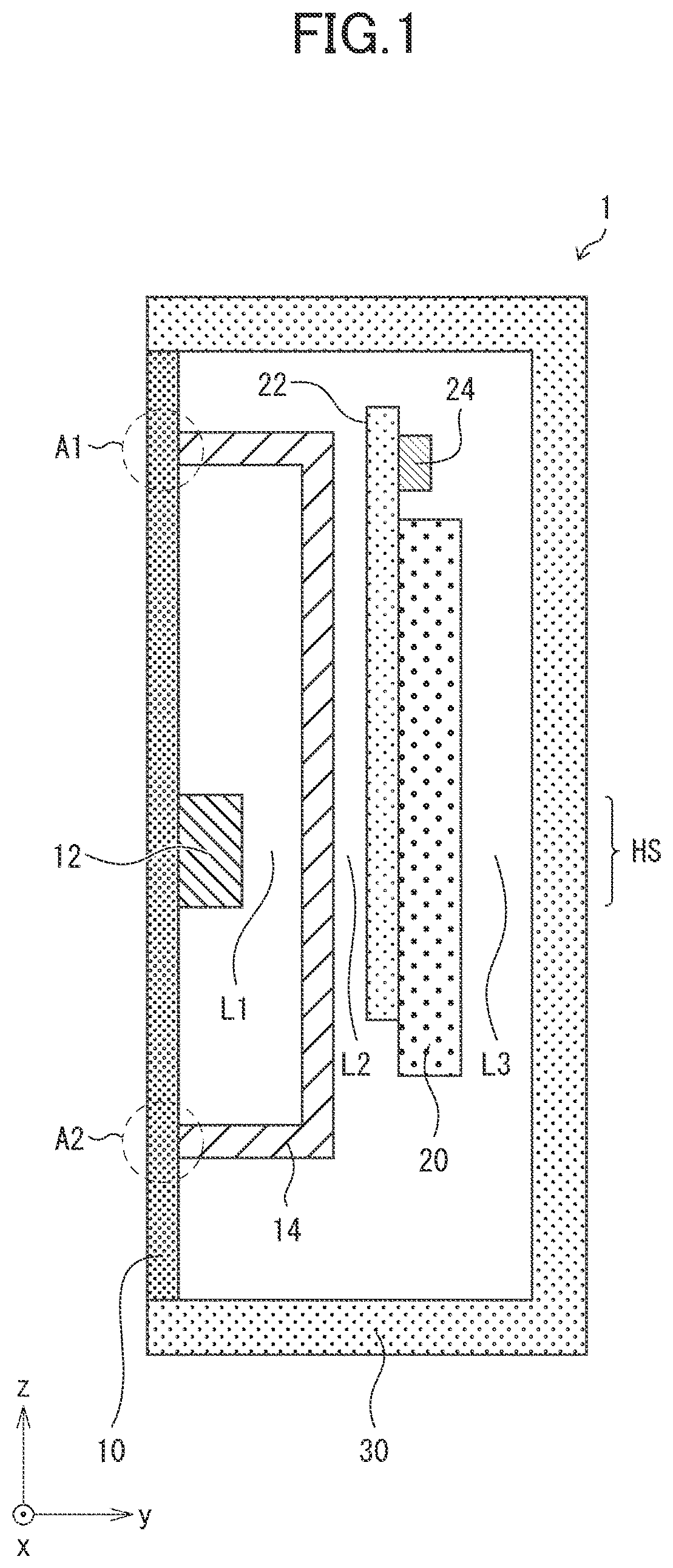
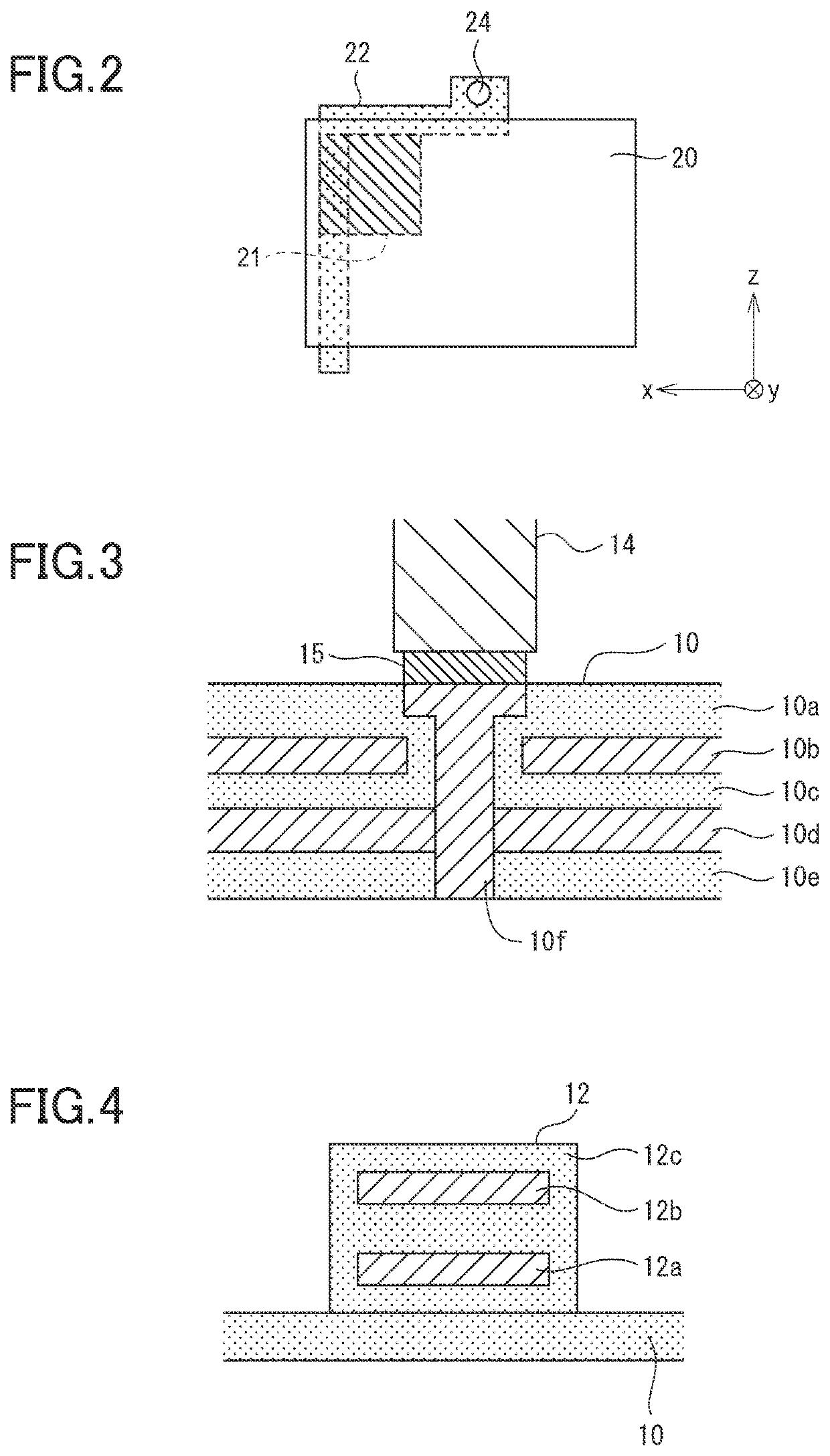
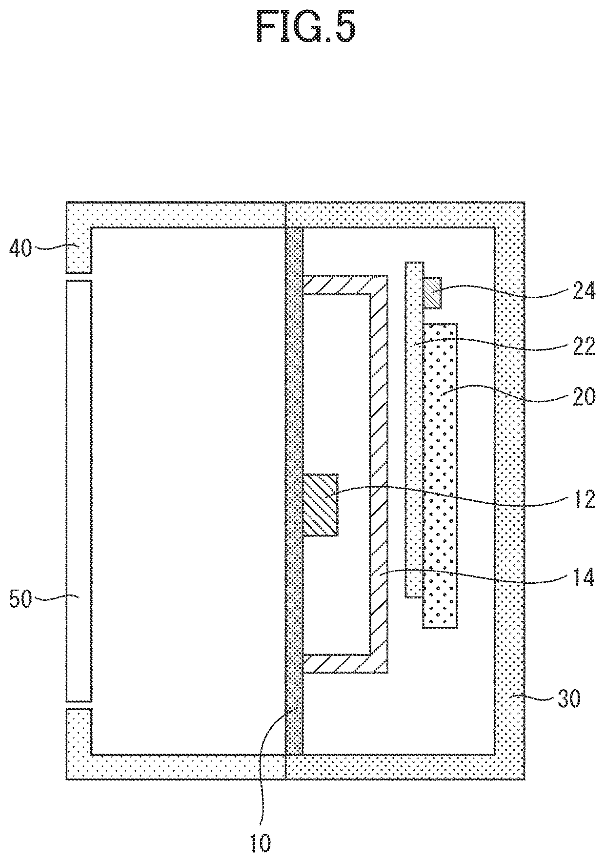
[0018]FIG. 1 is a sectional view of an electronic device 1 according to the present embodiment. As illustrated in FIG. 1, the electronic device 1 includes a first substrate 10, an electronic component 12, a heat dissipation member 14, a holding member 20, a second substrate 22, a thermistor 24, and a housing 30.

[0019]The electronic device 1 controls an arithmetic load of the electronic component 12 by referring to temperature detected by the thermistor 24 and thereby manages temperature of the housing 30 to be less than or equal to...

second embodiment

[0080]Next, a second embodiment will be described in detail with reference to FIGS. 7 and 8. Members that have been already described in the embodiment above will be given the same reference numerals, and description thereof will be omitted.

[0081]FIG. 7 is a sectional view of a portion of an electronic device 1a according to the present embodiment. As illustrated in FIG. 7, the electronic device 1a includes a holding member 20a instead of the holding member 20 provided in the electronic device 1 according to the first embodiment. The other configurations of the electronic device 1a are similar to those of the electronic device 1. FIG. 8 is a perspective view illustrating the holding member 20a and the thermistor 24.

[0082]As illustrated in FIGS. 7 and 8, an opening is formed in the holding member 20a, and the thermistor 24 is disposed in the opening. Here, the thermistor 24 is disposed such that the thermistor 24 is not in contact with an internal circumference of the opening. That i...


PUM


Abstract

An electronic device comprises an electronic component serving as a heat source; a first substrate on which the electronic component is disposed; a heat dissipation member that covers, with a first heat insulation layer in between, an area including a region of the first substrate, at which the electronic component is disposed, and being on a front side or a rear side of the first substrate; a housing that accommodates at least the first substrate and the heat dissipation member; a second substrate that faces the heat dissipation member across a second heat insulation layer in the housing; and a thermistor disposed on the second substrate.

Description

BACKGROUND1. Field[0001]An aspect of the present disclosure relates to an electronic device.2. Description of the Related Art[0002]In recent years, with improvement of performance of electronic devices, in particular, small and thin electronic devices such as smartphones, there have been growing concerns about a rise in temperature of a housing surface of an electronic device at the time of use or the like. Particularly, in new use cases such as 5G communication or recording by an 8K camera, the amount of power consumed by a CPU, a GPU, or the like is especially large, and therefore the temperature of the electronic device becomes locally high, resulting in generation of a heat spot having excessively high temperature.[0003]For example, Japanese Unexamined Patent Application Publication No. 2016-121985 describes a configuration in which a processor 5 disposed on a substrate of an electronic device acquires a first measurement value from a temperature sensor disposed on the substrate...

Claims


Application Information

Patent Timeline
IPC IPC(8): H05K7/20H01L23/373H01L23/367G01K7/42G01K7/16G05D23/24G05D23/19
CPCH05K7/20481H05K7/205H01L23/3735G05D23/1928G01K7/42G01K7/16G05D23/24H01L23/367H05K7/20509H01L23/3677H01L23/36G01K7/22G06F1/206G01K1/14
Inventor KUWAJIMA, HIDENORIIDE, TOMOYATANABE, HIROKI
Owner SHARP KK
Why Eureka
Try Eureka