
Distributed controllable heat source temperature field design method and system

A technology of heat source temperature and design method, applied in control/regulation system, temperature control, non-electric variable control, etc., can solve problems such as difficulty in obtaining surrounding heat sources, inability to control terminals to obtain information of multiple heat sources, and lack of coordination and cooperation of multiple heat sources. , to achieve the effect of reasonable temperature distribution, accurate heating temperature and pressure reduction

Inactive Publication Date: 2020-10-09
南京朝焱智能科技有限公司
View PDF0 Cites 0 Cited by
  • Summary
  • Abstract
  • Description
  • Claims
  • Application Information

AI Technical Summary

Problems solved by technology

[0002] Traditional temperature field unit control such as PLC control, all heat source information is uniformly transmitted to the PLC control memory, and then through the calculation and control of the microprocessor, only a single heat source is controlled, and it is difficult for a single heat source to obtain information about surrounding heat sources, thus lacking multiple The coordination and cooperation of heat sources; even if the information of surrounding heat sources can be obtained, relatively complex calculations and the interaction of a large amount of network data are required. Due to the delay of network transmission, it is impossible for the control terminal to obtain accurate multi-heat source information in real time

Method used


Image

  • Distributed controllable heat source temperature field design method and system
  • Distributed controllable heat source temperature field design method and system
  • Distributed controllable heat source temperature field design method and system

Examples


Embodiment Construction

[0044] In the following description, numerous specific details are given in order to provide a more thorough understanding of the present invention. It will be apparent, however, to one skilled in the art that the present invention may be practiced without one or more of these details. In other examples, some technical features known in the art are not described in order to avoid confusion with the present invention.

[0045] In the fields of metallurgy, chemical industry, etc., the operation of heating the workpiece is often encountered. The typical scene is to use fuel or electricity for heating. Under the control of PLC and other controllers, the controlled heat source is controlled to keep the workpiece The corresponding physical and chemical reactions are produced under constant temperature conditions. The applicant believes that all the heat sources in the traditional temperature field control system are centrally connected to the PLC control and controlled by the PLC c...


PUM


Abstract

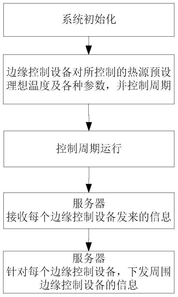
The invention discloses a distributed controllable heat source temperature field design method and system. The method comprises the steps of initializing each numerical value of a heat source system,presetting an ideal temperature for a controlled heat source through edge control equipment, and controlling a period; collecting information uploaded by the edge control equipment in the control cycle operation process; enabling a server to issue information detected by the peripheral edge control equipment according to the information uploaded by each piece of edge control equipment; and enabling the server to receive the information uploaded by each piece of edge control equipment, generate different temperature data and send the temperature data to each piece of edge control equipment, anda lot of edge control equipment being communicated with the server through the Ethernet. According to the invention, distributed heat source control adopted by a traditional temperature field is improved, so that the temperature field distribution is more reasonable; and the edge control equipment completes on-site calculation, so that the pressure of the server is reduced. The server can collectthe temperature of each temperature test point, and can count the time of each control point.

Description

technical field [0001] The invention belongs to the field of temperature field design, in particular to a distributed controllable heat source temperature field design method and system. Background technique [0002] Traditional temperature field unit control such as PLC control, all heat source information is uniformly transmitted to the PLC control memory, and then calculated and controlled by the microprocessor, only a single heat source is controlled, and it is difficult for a single heat source to obtain information about surrounding heat sources, thus lacking multiple The coordination and cooperation of heat sources; even if the information of surrounding heat sources can be obtained, relatively complex calculations and the interaction of a large amount of network data are required. Due to the delay of network transmission, it is impossible for the control terminal to obtain accurate multi-heat source information in real time. Contents of the invention [0003] Purpo...

Claims


Application Information

Patent Timeline
Patent Type & Authority Applications(China)
IPC IPC(8): G05D23/22
CPCG05D23/22
Inventor 鲁晓军
Owner 南京朝焱智能科技有限公司
Learn More