Orientable intravascular devices and methods

a technology of intravascular devices and methods, applied in the field of medical devices, can solve the problems of prolonging procedure times, stent rotation, and difficult to properly orient known devices and methods, and achieve the effect of facilitating proper positioning of side holes

Pending Publication Date: 2021-08-26
WALZMAN DANIEL EZRA
View PDF0 Cites 2 Cited by
  • Summary
  • Abstract
  • Description
  • Claims
  • Application Information

AI Technical Summary

Benefits of technology

[0036]As elaborated upon below, the interfaces between the devices facilitated by the aforementioned non-circular transverse cross-sectional configurations (e.g., the engagement between a wire and a catheter) inhibit (if not entirely prevent) relative rotation between the devices while allowing for relative axial (longitudinal) movement (e.g., sliding), even in those embodiments in which a stent may be located between the devices (e.g., over a portion of the wire). The devices described herein thus provide for adequate freedom of movement to permit the delivery of a catheter over a wire, or the delivery of a wire through a catheter, without undo force.
[0037]In some versions (e.g., in the context of branched stenting), a wire can be placed in each of first and second branches. The wire in the first branch may then be placed through a distal end hole of the delivery catheter and the catheter may be oriented such that a side-hole in the catheter is positioned at (or adjacent to) a stent side fenestration. The wire in the second branch can then be backloaded into the side-hole (e.g., to facilitate proper positioning of the side-hole relative to the origin of the side branch while maintaining wire access to the side branch).

Problems solved by technology

Known devices and methods are difficult to properly orient due to several factors, particularly in the context of tortuous vasculature.
As a result, stents will generally be caused to rotate during deployment in an unpredictable fashion.
Additionally, as catheters are advanced through tortuous anatomy, the catheters themselves can rotate (twist), and do so in an unpredictable fashion.
Achieving the desired radial placement can therefore be cumbersome and can results in extend procedure times, improper placement, and other negative consequences.

Method used


Image

  • Orientable intravascular devices and methods
  • Orientable intravascular devices and methods
  • Orientable intravascular devices and methods

Examples


Embodiment Construction

[0214]The embodiments of the device and variants of the device of the present disclosure are set forth with reference to the above drawings.

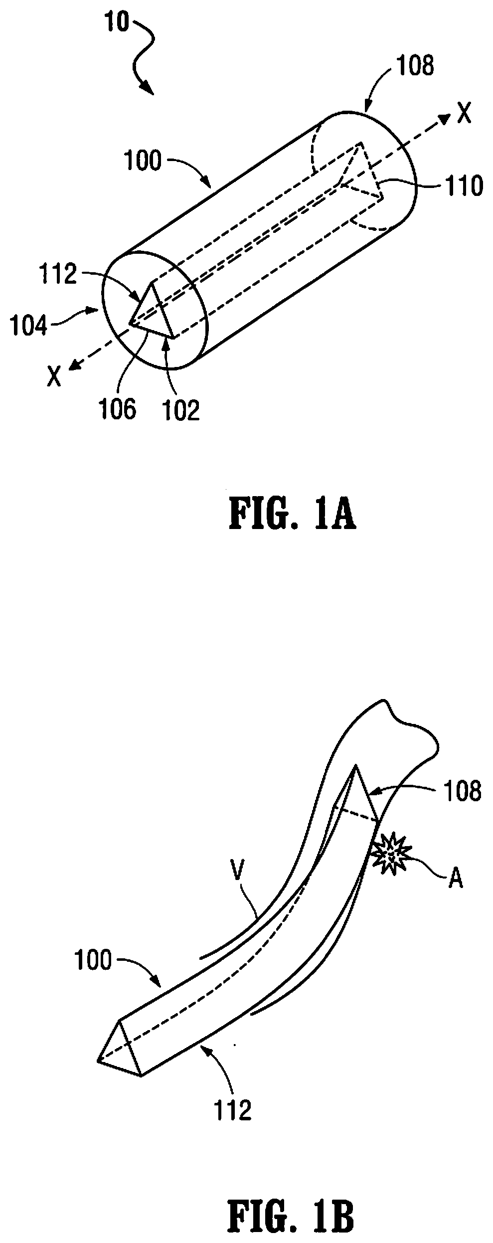
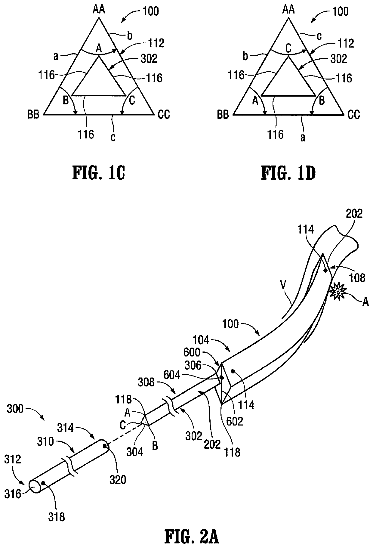
[0215]Referring to FIG. 1A, the delivery catheter 100 is illustrated. As discussed above, the aforementioned lumen 112 extends through the delivery catheter 100 and includes a (first) non-circular transverse (lateral) cross-sectional configuration. Although the transverse (lateral) cross-sectional configuration of the lumen 112 is shown as being (generally) triangular in FIG. 1A, a variety of other non-circular transverse (lateral) cross-sectional configurations are also contemplated by the present disclosure including, for example, rectangular, pentagonal, hexagonal, octagonal, square-shaped, ovate (elliptical), stars-shaped, arrow-shaped, etc., as mentioned above. The lumen 112 is configured to (slidably) receive an (elongated) medical device, such as, for example, the pusher 302 (FIG. 2A) of the packaging catheter 300, the balloon catheter 40...


PUM


Abstract

An orientable intravascular device having a “twelve o'clock” marker on a proximal and distal end for treating an aneurysm, including a packaging catheter with an identical fixed non-circular shaped inner lumen, a pusher wire having an occlusion device releasably disposed on the distal end of said pusher wire, pre-loaded at a fixed circumferential orientation, with corresponding markers on the outside of said packaging catheter, a hub having an inner lumen that is shaped to marry with the outer lumen of the packaging catheter to deliver a delivery wire and occlusion stent in a predicted orientation, and maintaining such orientation as the wire and stent are advanced through said delivery catheter, and while said delivery catheter is withdrawn. Methods of using same are disclosed.

Description

CROSS-REFERENCE TO RELATED APPLICATION(S)[0001]This application claims priority to provisional application 63 / 109,387, filed on Nov. 4, 2020, and is a continuation-in-part of U.S. application Ser. No. 16 / 888,813, filed on May 31, 2020, which claims priority from provisional application No. 62 / 921,574, filed Jun. 25, 2019, and is a continuation-in-part of U.S. application Ser. No. 16 / 852,488, filed on Apr. 19, 2020, which claims priority to provisional application 62 / 921,378, filed Jun. 12, 2019. The entire contents of each of these applications are hereby incorporated herein by reference.FIELD OF THE INVENTION[0002]The present disclosure relates to medical devices used to treat vascular pathologies (e.g., aneurysms, fistulas, ruptures, etc.) in intracranial or other tortuous blood vessels (vasculature). In one particular aspect, for example, the present disclosure relates to endovascular devices that are configured to deploy a stent (e.g., a flow-diverting stent, a covered stent, a ...

Claims


Application Information

Patent Timeline
Patent Type & Authority Applications(United States)
IPC IPC(8): A61F2/852A61F2/958
CPCA61F2/852A61F2002/823A61F2/958A61F2/82A61F2/954A61F2230/0023A61M25/0023A61B2090/3966
Inventor WALZMAN, DANIEL EZRA
Owner WALZMAN DANIEL EZRA
Why Eureka
Try Eureka