Reciprocating Gas Compressor Valve
a gas compressor and valve body technology, applied in the direction of machines/engines, liquid fuel engines, positive displacement liquid engines, etc., can solve the problems of obstructing the reverse flow, and inefficient operation of the valve body
- Summary
- Abstract
- Description
- Claims
- Application Information
AI Technical Summary
Benefits of technology
Problems solved by technology
Method used
Image

Examples
example i
Increased Flow Area
[0173]Certain prior art valves utilize press fitted cartridges into the seat and one end of the cartridge serves as the sealing surface for the sealing element. The number of cartridges contained in the valve 100 is directly proportional to the diameter of the seat 10. In these prior art valves, the seat has a series of holes that are drilled into the seat to maximize the amount of flow area and serve as the inlet to the reciprocating gas compressor valve. Equivalent flow area is used to compare valves of similar dimensions.
[0174]To calculate this area, the reciprocating gas compressor valve 100 is considered as a fabrication of three orifices in series. A discharge coefficient can be calculated by testing this valve in a flow tunnel. The discharge coefficient in this example is considered as one. The three orifice areas are described as seat area, lift area and guard area. The seat area is defined as the summation of all open spaces in a seat in the axial directi...
example ii
Percent Reduction in Clearance
[0177]Clearance volume is the residual space in the compressor cylinder occurring at the end of the stroke. Clearance comprises spaces in the valve recess and the space between the piston and the cylinder end. High clearance results in more residual gas trapped at end of each stroke, resulting in lower volumetric efficiency. Lower clearance is desired because it increases the volumetric efficiency of the compressor and associated processes.
[0178]In addition to compromising the seat strength, when large holes are required in a reciprocating gas compressor valve, the height of the seat has to be increased. As large diameter holes assist to increase flow area, the height of the seat has to be increased to compensate for a reduction in structural strength. Increasing the height expands the open space in the valve and results in enlarged dead volumes. Gas can then migrate into these dead volumes during compression cycle resulting in reduced throughput. The d...
example iii
Reciprocating Gas Compressor Test
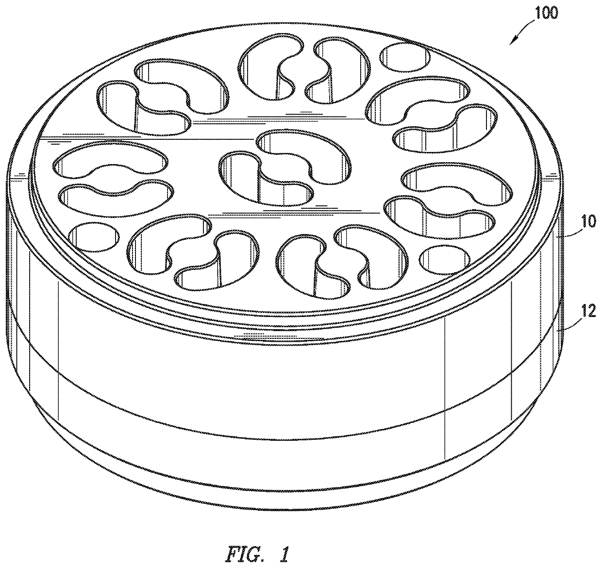
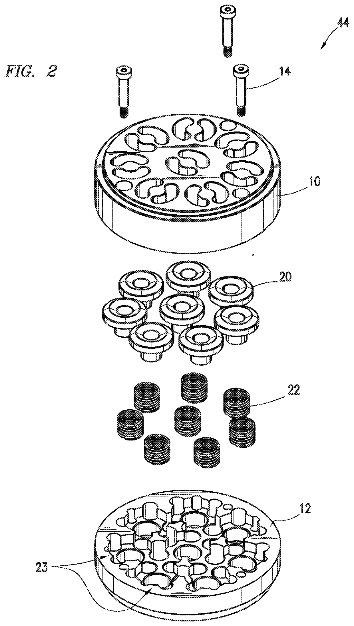
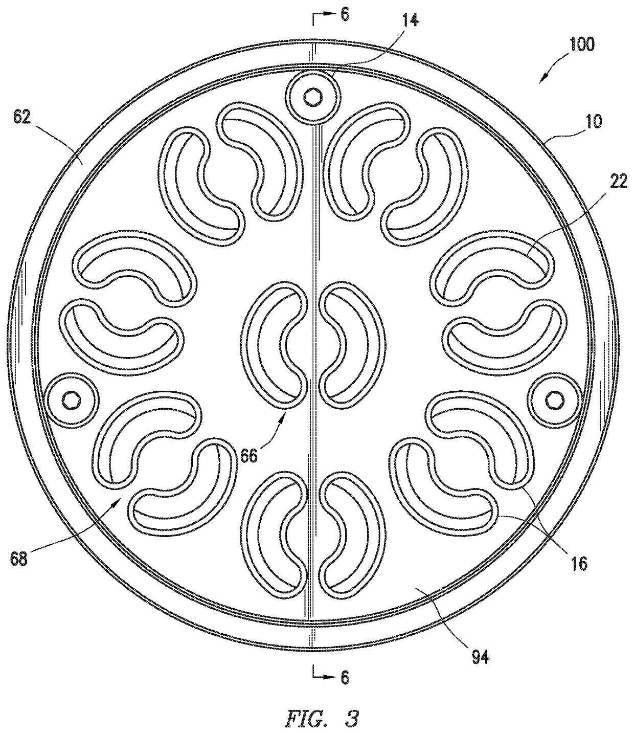
[0182]The reciprocating gas compressor valves both existing and the reciprocating gas compressor valve shown in FIGS. 1 to 6 having a sealing with the design shown in FIGS. 18 to 22 were manufactured for compressor testing in a single cylinder, double acting, reciprocating compressor. The compressor is instrumented with pressure taps at critical locations. In our testing, temperature readings were taken by inline gas measurement device. A 500 hp electric motor was used to drive this compressor. A VFD drive was used to control the test speed. Nitrogen was used as the test fluid. This compressor had a complete loop with a cooling tower. Test was performed at 700 rpm with a pressure ratio of 2.0. Suction and discharge pressures were maintained at 100 psi and 215 psi respectively.
[0183]Data (flow, multiple pressures and temperatures) was collected by the electronic data analyzer using the various pressure taps and analyzed to check for any abnormalities....
PUM
 Abstract
Description
Claims
Application Information
 - R&D
- Intellectual Property
- Life Sciences
- Materials
- Tech Scout
- Unparalleled Data Quality
- Higher Quality Content
- 60% Fewer Hallucinations
Browse by: Latest US Patents, China's latest patents, Technical Efficacy Thesaurus, Application Domain, Technology Topic, Popular Technical Reports.
© 2025 PatSnap. All rights reserved.Legal|Privacy policy|Modern Slavery Act Transparency Statement|Sitemap|About US| Contact US: help@patsnap.com