Damper assembly and a housing for the damper assembly

a technology of damper assembly and housing, which is applied in the direction of spring/damper functional characteristics, shock absorbers, transportation and packaging, etc., can solve the problems of inability to provide continuously variable damping, many known controllable dampers are limited in response, and many known controllable dampers are not suitable for real-time systems. , to achieve the effect of reducing manufacturing costs, minimizing fluid flow distance, and simple design

Active Publication Date: 2021-08-26
BEIJINGWEST INDUSTRIES
View PDF11 Cites 0 Cited by
  • Summary
  • Abstract
  • Description
  • Claims
  • Application Information

AI Technical Summary

Benefits of technology

[0006]The present invention in its broadest aspect provides a damper assembly having a simplistic design thereby reducing the manufacturing cost for the damper assembly. The present invention also minimizes fluid flow distance in the compartment of the damper assembly to reduce flow restrictions. In addition, the present invention provides a damper assembly having an improved operation life by preventing damages to the main piston. Furthermore, the present invention eliminates air entrapment in the damper assembly.

Problems solved by technology

Due to small electric actuators and the high friction of the movable members, many known controllable dampers are limited in response time, and are not suitable for real time systems.
In addition, many devices select from a limited group of discrete settings and are not capable of providing continuously variable damping.

Method used


Image

  • Damper assembly and a housing for the damper assembly
  • Damper assembly and a housing for the damper assembly
  • Damper assembly and a housing for the damper assembly

Examples


Embodiment Construction

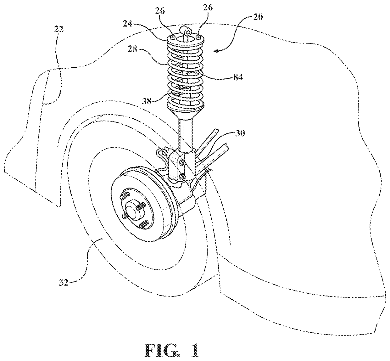
[0016]Referring to the Figures, wherein like numerals indicate corresponding parts throughout the several views, a damper assembly 20 for use in a vehicle constructed in accordance with one embodiment of the present invention is generally shown in FIG. 1.

[0017]FIG. 1 illustrates a fragment of an exemplary vehicle suspension including the damper assembly 20 being attached to a vehicle chassis 22 via a top mount 24 and a number of screws 26 disposed on a periphery of an upper surface of the top mount 24. The top mount 24 connects to a coil spring 28. The damper assembly 20 connects to the steering knuckle 30 supporting vehicle wheel 32.

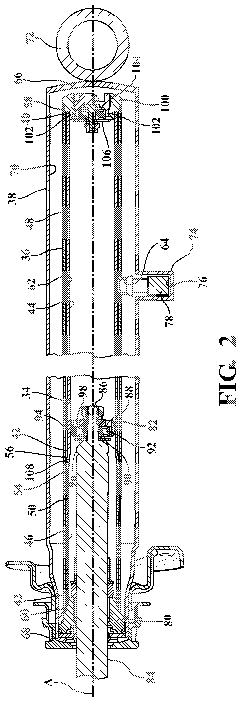
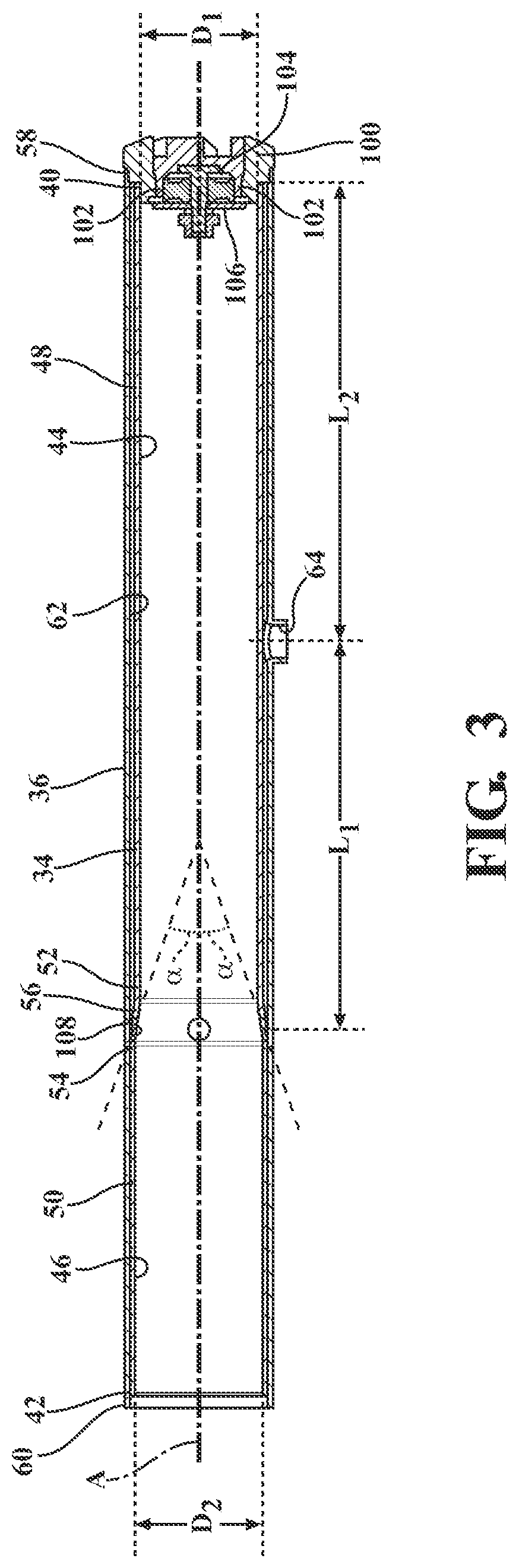
[0018]As best shown in FIG. 2, the damper assembly 20 comprises a housing 34, 36, 38. The housing 34, 36, 38 includes a main tube 34, a sleeve 36, and an external tube 38 disposed in a concentric relationship with one another. The main tube 34, having a generally cylindrical shape, extends along a center axis between a first end 40 and a second end 42. ...


PUM


Abstract

A damper assembly comprises a main tube defining a fluid chamber. The main tube includes a first section, a second section, and an intermediate portion. A sleeve is disposed about the main tube. An external tube is disposed about the main tube and the sleeve. The external tube defines a compensation chamber between the sleeve and the external tube. A main piston divides the fluid chamber into a rebound chamber and a compression chamber. A piston rod couples to the main piston for moving the main piston between a compression stroke and a rebound stroke. The sleeve is in an abutment relationship with the second section of the main tube, radially spaced apart from the first section of the main tube, defining a compartment extending between the sleeve and the first section of the main tube. A housing for the damper assembly is also disclosed herein.

Description

CROSS REFERENCE TO RELATED APPLICATION[0001]The present application claims the benefit of U.S. Provisional Patent Application Ser. No. 62 / 981,423, filed on Feb. 25, 2020, and Chinese Application No. 202011403810.3 filed on Dec. 4, 2020, the entire disclosures of which are hereby incorporated herein by reference.BACKGROUND OF THE INVENTION1. Field of the Invention[0002]The present invention relates generally to a damper assembly and a housing for the damper assembly.2. Description of the Prior Art[0003]There are a variety of dampers in automotive suspensions, including a mono-tube type strut, a twin-tube type dampers, and a triple-tube type dampers. Within each variation, there are variations with valve arrangement and fluid management. The triple-tube type damper construction includes tube and valve arrangement that allows for fluid flow within the damper that is generally in a single direction for both the compression and rebound direction of the suspension damper, whereas both mon...

Claims


Application Information

Patent Timeline
Patent Type & Authority Applications(United States)
IPC IPC(8): F16F9/32F16F9/18F16F9/36F16F9/48
CPCF16F9/3235F16F9/18B60G13/08F16F9/483F16F9/364F16F9/185F16F9/32F16F9/3257F16F9/3207F16F9/3221F16F9/3214F16F9/34F16F9/3481F16F9/3482F16F9/3484F16F2226/045B60G17/08B60G15/062B60G2202/24B60G2500/11B60G2206/41B60G2204/62B60G2206/82092B60G2500/104B60G2800/162F16F9/50F16F2222/12F16F2228/066F16F2230/0023F16F2232/08F16F2234/02
Inventor LUN, SAIMANDELLAC, PHILIPPEPTAK, MICHAL
Owner BEIJINGWEST INDUSTRIES
Why Eureka
Try Eureka