Single trip liner hanger system

a single-trip, hanging system technology, applied in the direction of drilling casings, drilling pipes, borehole/well accessories, etc., can solve the problems of increasing cost, time and risk, restricting the inner diameter of both the running tool and the work string,

Active Publication Date: 2021-09-23
PACKERS PLUS ENERGY SERVICES INC
View PDF1 Cites 0 Cited by
  • Summary
  • Abstract
  • Description
  • Claims
  • Application Information

AI Technical Summary

Benefits of technology

[0013]The liner hanger deployment system detailed below negates the need to perform multiple trips to deploy a liner. The liner hanger deployment system operates by deploying a liner hanger on full bore casing, without using the restricted-diameter running tools and work strings associated with conventional liner hanger deployment systems. The liner hanger deployment system detailed below also provides pressure integrity between the casing's inner and outer diameter from the liner top to the wellhead.

Problems solved by technology

The inner diameter of both the running tool and the work string is restricted, which is problematic.
For example, a restricted inner diameter does not allow for a rate of fluid flow that is as high as often desired.
These additional procedures—pulling the work string and running tool out of the wellbore, and then deploying a tieback casing string into the wellbore to connect with the liner hanger—increase cost, time and risk.
Additional procedures cost time and money.
As discussed later in connection with FIG. 1, disengagement of the running tool from the liner hanger, withdrawal of the liner hanger and work string from the wellbore, and then deployment of the tieback casing string into the wellbore, all add risk.
One such risk for example occurs when the running tool cannot be separated from the liner hanger.
Such risks might lead to costly emergency contingency actions.

Method used


Image

  • Single trip liner hanger system
  • Single trip liner hanger system
  • Single trip liner hanger system

Examples


Embodiment Construction

[0027]It should be noted that terms “upper”, “back”, “rear”, or “uphole” are used to refer to a feature on or closer to the surface side (upwell side) relative to a corresponding feature that is farther from the surface side, which farther feature is denoted by the terms “lower”, “forward”, “front” or “downhole”. For example, an “upper” end of a tubular generally refers to the feature relatively closer to the surface than a corresponding “lower” end. A feature that may be referred to as an“upper” feature relative to a “lower” feature even if the features are vertically aligned may occur, for example, in a horizontal well. Similarly, the terms “uphole”, “up”, “downhole” and “down” refer to the relative position or movement of various tools or objects, features, with respect to the wellhead.

[0028]It is to be understood that variants of the embodiments described and illustrated in this specification will become readily apparent to those skilled in the art.

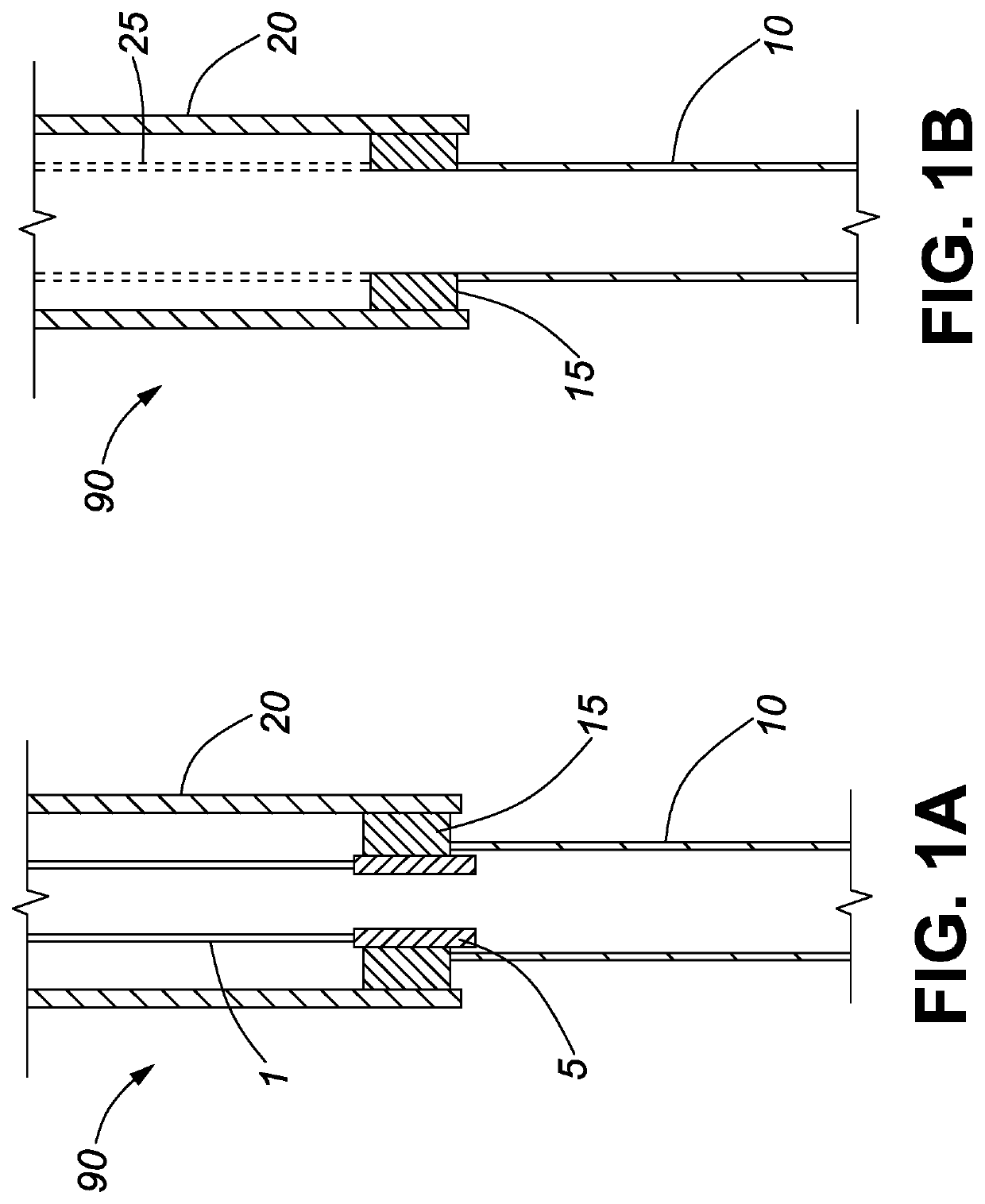
[0029]FIG. 1 illustrates a con...


PUM


Abstract

A liner hanger system enables installation of a liner hanger by means of a full bore casing to surface and provides pressure integrity between the casing's inner and outer sides. The liner hanger system comprises a liner hanger, along with an associated liner, coupled to a tieback casing string. The liner hanger and liner are deployed downhole connected to a tieback casing string. Once the liner has been lowered to the position of interest, first the liner hanger is anchored and cemented in position, and then, a packer is set to seal the lower annulus of the liner. The liner hanger system enables operations that used to require a plurality of trips, to be performed in a single trip. It does so without introducing any unwanted limitation to the inner diameter at any point between the wellhead and the end of the liner, and while also allowing for potential decoupling and removal of the tieback casing string from the liner hanger if desired.

Description

RELATED PATENT APPLICATIONS[0001]This patent application claims priority from U.S. Provisional Patent Application 62 / 993,626, filed Mar. 23, 2020.TECHNICAL FIELD[0002]The present disclosure relates generally to equipment utilized in conjunction with wellbore construction, completion and production operations. More particularly, the embodiments disclosed herein provide a liner hanger system in which multiple operations for installing liners in a wellbore can be achieved in a single trip.BACKGROUND[0003]When performing petroleum completion operations, a wellbore is drilled and completed to facilitate removal of desired hydrocarbons from a subterranean formation. Once a wellbore is drilled, steel casing or other types of casing may be inserted into the wellbore. Cement may then be pumped into the annulus formed between the casing and the wellbore, in order to prevent migration of fluids or gases in the annulus formed between the casing and the wellbore wall.[0004]Once an upper portion ...

Claims


Application Information

Patent Timeline
Patent Type & Authority Applications(United States)
IPC IPC(8): E21B43/10E21B23/06
CPCE21B43/105E21B23/06E21B43/106E21B43/10E21B23/01E21B17/021E21B17/042E21B33/12
Inventor BOLIVAR, JAVIERFREDERICKS, BRIAN
Owner PACKERS PLUS ENERGY SERVICES INC
Why Eureka
Try Eureka