Pressure booster

Inactive Publication Date: 2021-09-23
SMC CORP
View PDF0 Cites 0 Cited by
  • Summary
  • Abstract
  • Description
  • Claims
  • Application Information

AI Technical Summary

Benefits of technology

[0014]In this manner, by using the first solenoid valve and the second solenoid valve, switching of the direction of movement of the first piston, the piston rod, and the second piston is carried out electrically, and thus the internal structure of the pressure booster can be further simplified.
[0015]In this case, the fluid supplying mechanism may further include a first inlet check valve provided in the first supply flow passage and configured to prevent back-flowing of the fluid from the first pressure boosting chamber, and a second inlet check valve provided in the second supply flow passage and configured to prevent back-flowing of the fluid from the second pressure boosting chamber. In accordance with this feature, in the first pressure boosting chamber and the second pressure boosting chamber, the pressure of the fluid can be reliably increased.
[0016]Further, the pressure booster further includes a fluid output mechanism configured to output to the exterior the fluid which was boosted in pressure in the first pressure boosting chamber or the second pressure boosting chamber. In this case, the fluid output mechanism may be configured to include a first outlet check valve configured to prevent back-flowing of the fluid into the first pressure boosting chamber, and a secon

Problems solved by technology

However, in a conventional pressure booster, in order to prevent the pistons from being stopped midway during the pressure boosting operation, a drive mechanism (stop prevention mechanism) having a multilayer structure by a mechanical mechanism is provided, and thus, the internal s

Method used


Image

  • Pressure booster
  • Pressure booster
  • Pressure booster

Examples


Example

[0030]A preferred embodiment of a pressure booster according to the present invention will be described in detail below with reference to the drawings.

Configuration of Present Embodiment

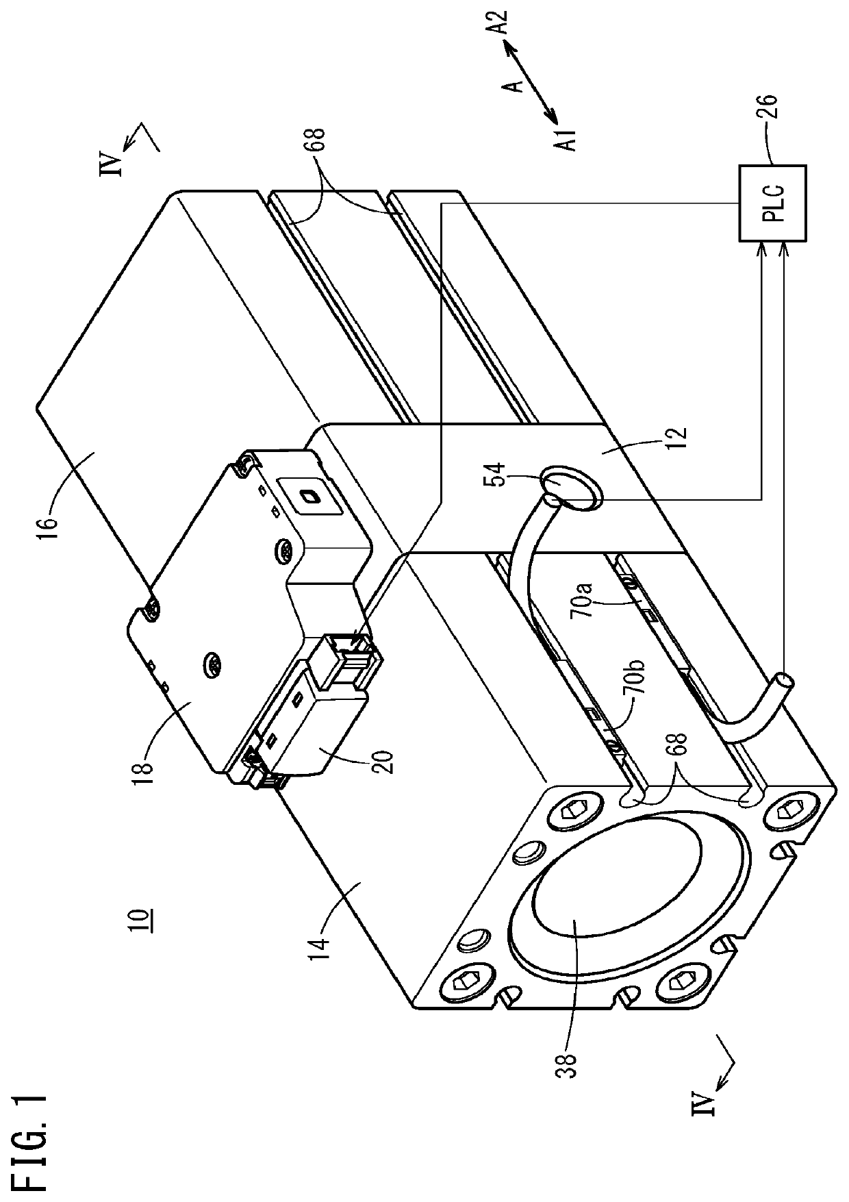
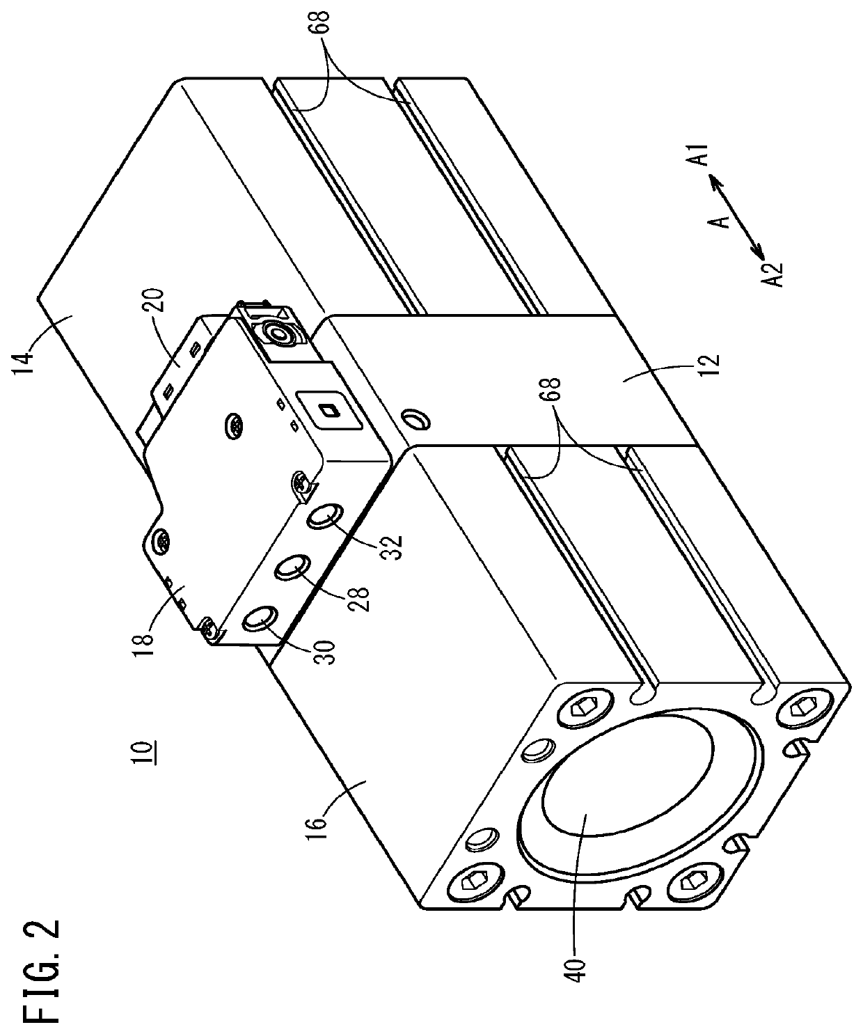
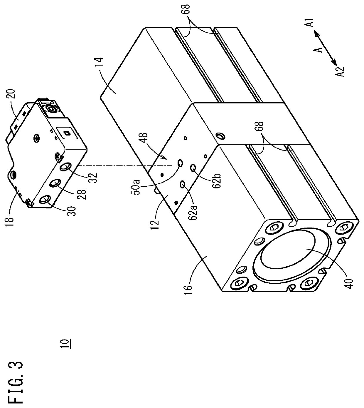
[0031]As shown in FIGS. 1 to 5, a pressure booster 10 according to the present embodiment includes a tandem type cylinder structure in which a first cylinder 14 is disposed contiguously on one end side (a side in the A1 direction) of a center body 12, and a second cylinder 16 is disposed contiguously on another end side (a side in the A2 direction) of the center body 12. Accordingly, in the pressure booster 10, the first cylinder 14, the center body 12, and the second cylinder 16 are disposed contiguously in this order from the A1 direction toward the A2 direction. Moreover, the outer peripheral surfaces of the first cylinder 14, the center body 12, and the second cylinder 16 are formed substantially flush with each other.

[0032]A block-shaped control unit 18 is disposed on an upper surface of the cen...


PUM


Abstract

A first position detection sensor and a second position detection sensor of a pressure booster detect the position of a first piston or a second piston. A fluid supply mechanism supplies a fluid to a first pressure-boosting chamber and/or a second pressure-boosting chamber. On the basis of the detection results of the first position detection sensor and the second position detection sensor, the fluid supply mechanism switches between performing an operation for supplying fluid to a first drive chamber and discharging fluid from a second drive chamber, and performing an operation for discharging fluid from the first drive chamber and supplying fluid to the second drive chamber.

Description

TECHNICAL FIELD[0001]The present invention relates to a pressure booster adapted to increase the pressure of a fluid.BACKGROUND ART[0002]With the object of supplying a high pressure fluid to a fluid pressure apparatus, a pressure booster, which increases the pressure of a supplied fluid, and outputs the fluid after having been boosted in pressure to the exterior, has been disclosed, for example, in Japanese Laid-Open Patent Publication No. 09-158901, Japanese Laid-Open Patent Publication No. 2008-223841, Japanese Laid-Open Patent Publication No. 2002-039105, Japanese Laid-Open Patent Publication No. 2001-311404, Japanese Laid-Open Patent Publication No. 10-267001, Japanese Laid-Open Patent Publication No. 10-267002, and Japanese Laid-Open Utility Model Publication No. 05-075501.[0003]In such pressure boosters, a piston rod extends into a first chamber and a second chamber inside a cylinder, and by a first piston connected to one end of the piston rod inside the first chamber, and a ...

Claims


Application Information

Patent Timeline
IPC IPC(8): F15B3/00
CPCF15B3/00F15B2211/6336F15B2211/77F15B2211/7055F15B2211/665
Inventor ASAHARA, HIROYUKIMONDEN, KENGOSHINJO, NAOKINAGURA, SEIICHISOMEYA, KAZUTAKA
Owner SMC CORP
Why Eureka
Try Eureka