
Bearing device for vehicle wheel

Active Publication Date: 2021-09-23
NTN CORP
View PDF0 Cites 0 Cited by
  • Summary
  • Abstract
  • Description
  • Claims
  • Application Information

AI Technical Summary

Benefits of technology

The bearing device for a vehicle wheel described in this patent text has several technical effects. Firstly, the design of the fitting section prevents interference with the inner edge of the fitting hole in the vehicle body when the fitting cylinder section is fitted in, improving the assembly process. Secondly, a tapered portion on the outer edge of the fitting section prevents the cap member from falling off during use. Thirdly, the design ensures that even when the fitting section is pushed strongly to the small-diameter section to prevent falling off, it still does not interfere with the inner edge of the fitting hole, further improving the assembly process. Additionally, the device includes an encoder and sensor to detect the position of the wheel during use, and the cover plate section of the cap member is designed to ensure accurate detection of the position without distortion.

Problems solved by technology

When muddy water enters into this annular space, the raceway surface and the rolling member are damaged by dust and the like contained in the muddy water, which results in shortening of a bearing life.
However, when the fitting section of the cap member is opened radially outward due to spring back or the like, this fitting section may interfere with an inner peripheral edge of the fitting hole section and may not be fitted smoothly (see FIG. 8).

Method used


Image

  • Bearing device for vehicle wheel
  • Bearing device for vehicle wheel
  • Bearing device for vehicle wheel

Examples


first embodiment

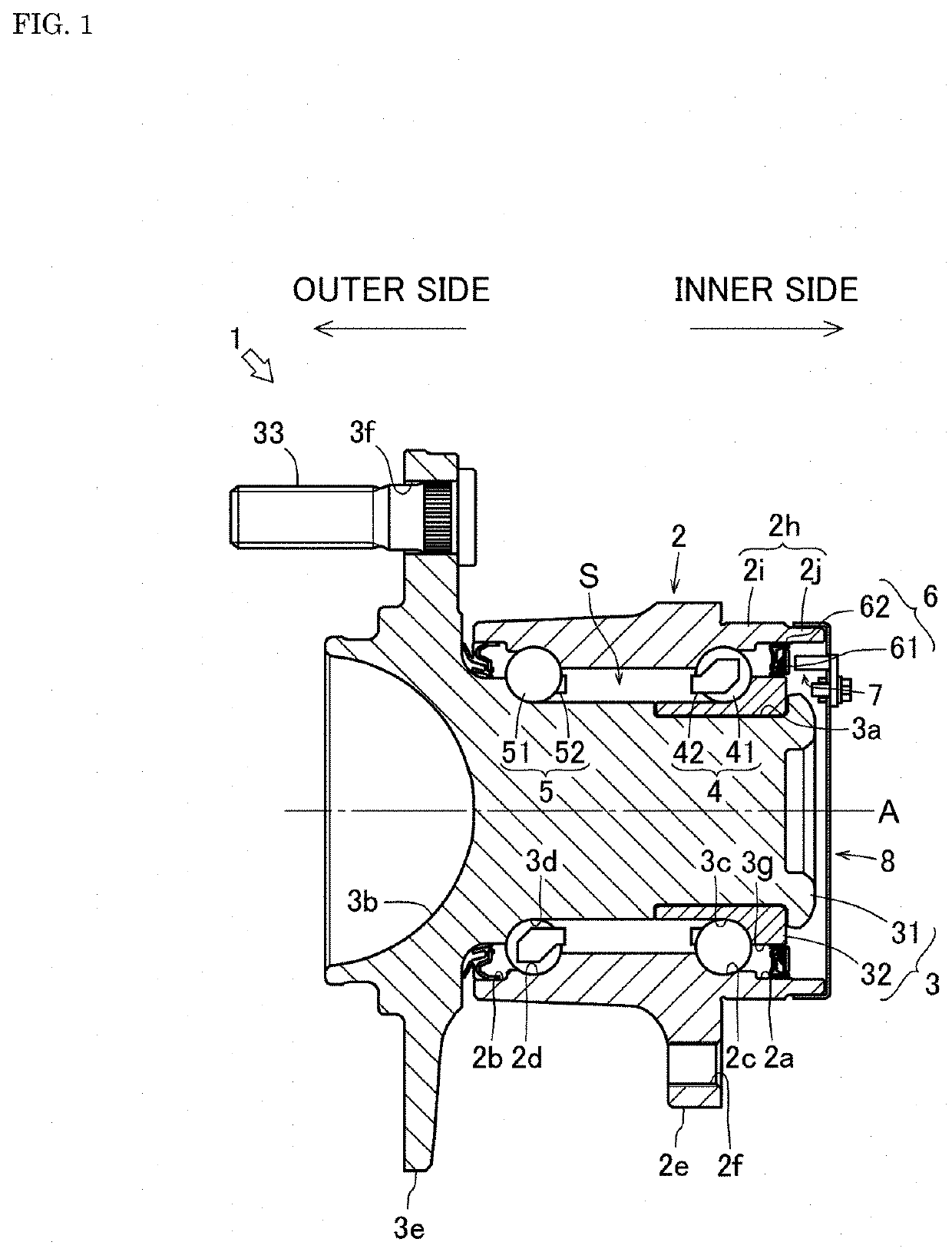
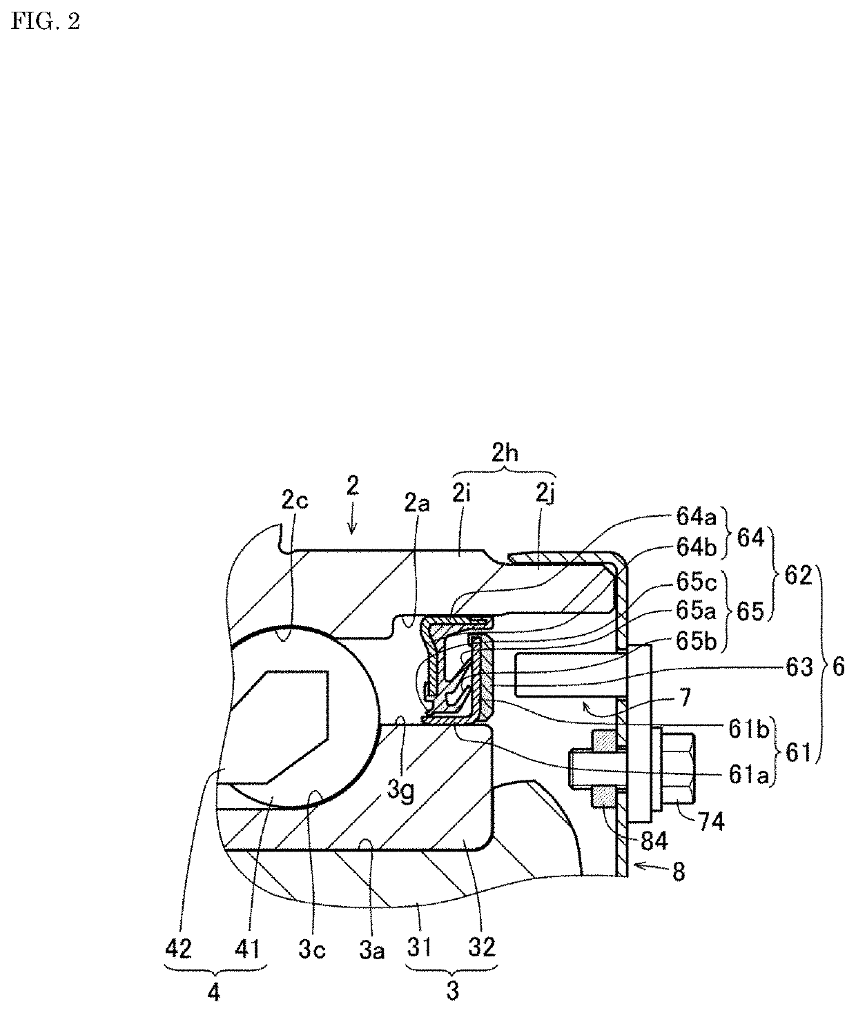
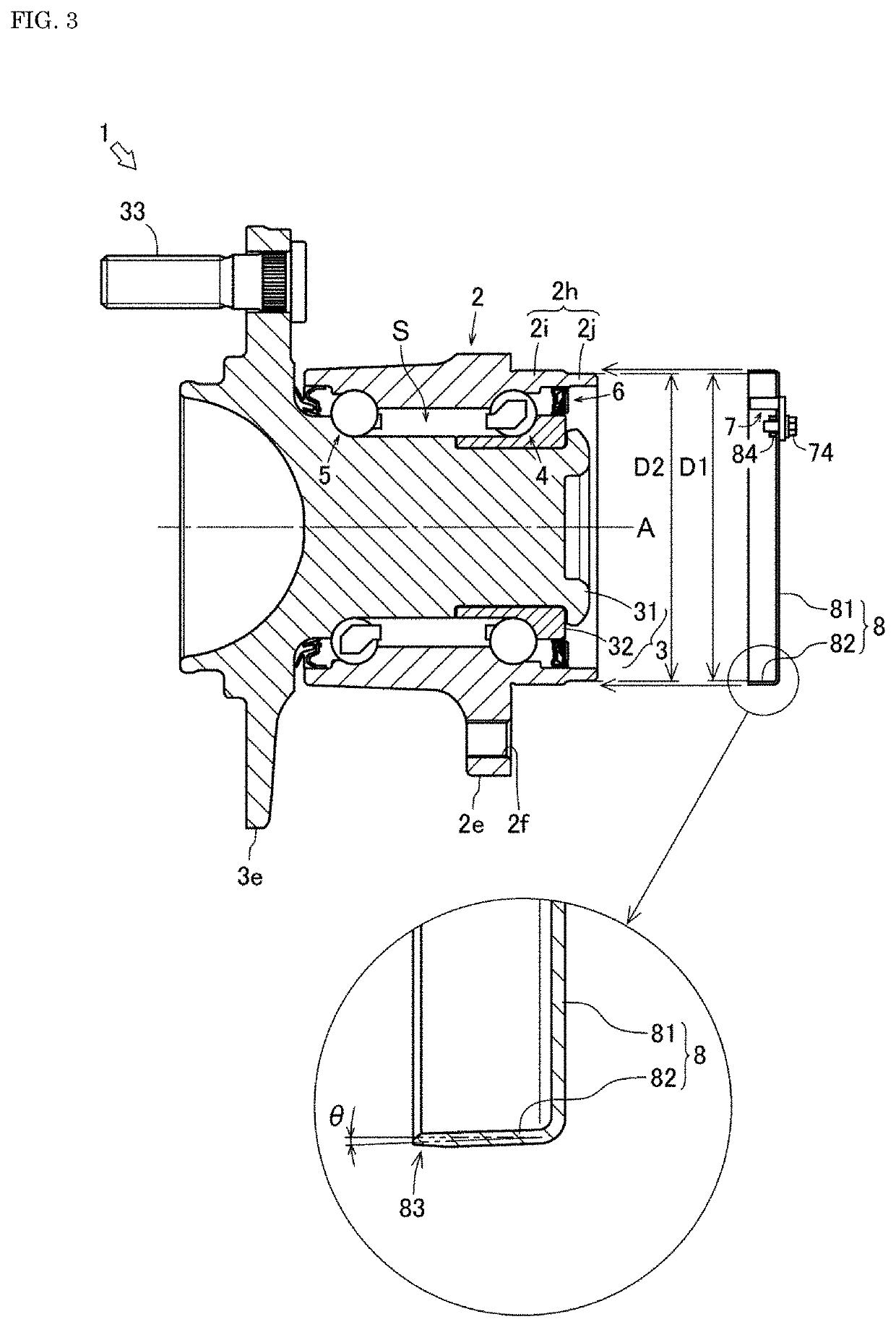
[0065]As described above, in the bearing device for a vehicle wheel 1 provided with the cap member 8 the large-diameter section 2i is formed on the outer side of the fitting cylinder section 2h, and the small-diameter section 2j is formed on the inner side of the fitting cylinder section 2h. Then, the cap member 8 is formed by bending a metal steel plate, to have the cover plate section 81 that closes the inner open end of the outer member 2 and have the fitting section 82 that is fitted over the small-diameter section 2j, and to be provided with the tapered portion 83 based on the spring back angle θ of the fitting section 82, on the outer peripheral edge at the outer end section of the fitting section 82. According to such a bearing device for a vehicle wheel 1, the fitting section 82 of the cap member 8 does not interfere with the inner peripheral edge of the fitting hole section 9h when the fitting cylinder section 2h of the outer member 2 is fitted into the fitting hole sectio...

second embodiment

[0069]As described above, in the bearing device for a vehicle wheel 1 provided with the cap member 8 when an angle of the outer peripheral surface 82s of the fitting section 82 with respect to the rotation axis A of the inner member 3 is R1, and an angle of the inclined surface 83s of the tapered portion 83 with respect to the outer peripheral surface 82s of the fitting section 82 is R2, a relational expression R1≤R2 is satisfied. According to such a bearing device for a vehicle wheel 1, it is possible to reliably prevent the fitting section 82 of the cap member 8 from interfering with the inner peripheral edge of the fitting hole section 9h. Therefore, it is possible to further improve the assembling property of the automobile.

[0070]Next, features and effects of a cap member 8 according to a third embodiment will be described. However, only a part different from the cap member 8 according to the second embodiment will be described. FIG. 7 is a view showing a main part shape of the...

third embodiment

[0072]As described above, in the bearing device for a vehicle wheel 1 provided with the cap member 8 when an inner diameter of the fitting section 82 is D1, an outer diameter of a small-diameter section 2j is D2, an outer diameter of the fitting section 82 is D3, and an outer diameter of the large-diameter section 2i is D4, the relational expression D1≤D2 and the relational expression D3≤D4 are satisfied. According to such a bearing device for a vehicle wheel 1, even with a design in which the fitting section 82 is pushed strongly to the small-diameter section 2j to prevent falling off, it is possible to reliably prevent the fitting section 82 of the cap member 8 from interfering with the inner peripheral edge of the fitting hole section 9h. Therefore, it is possible to prevent the cap member 8 from falling off, and further improve the assembling property of the automobile.

[0073]Next, other features and effects of the cap member 8 according to each embodiment will be described.

[007...


PUM


Abstract

In a bearing device for a vehicle wheel (1), a large-diameter section (2i) is formed on an outer side of a fitting cylinder section (2h), and a small-diameter section (2j) is formed on an inner side of the fitting cylinder section (2h). A cap member (8) is formed by bending a metal steel plate, and has a cover plate section (81) which closes the inner open end of an outer member (2) and a fitting section (82) which is fitted over the small-diameter section (2j). A tapered portion (83) based on the spring back angle θ of the fitting section (82) is provided at the outer peripheral edge of the outer end section of the fitting section (82).

Description

TECHNICAL FIELD[0001]The present invention relates to a bearing device for a vehicle wheel.BACKGROUND ART[0002]Conventionally, a bearing device for a vehicle wheel that rotatably supports a wheel has been known. In the bearing device for a vehicle wheel, an inner member is arranged inside an outer member, and a rolling member is interposed between respective raceway surfaces of the outer member and the inner member. In this way, the bearing device for a vehicle wheel forms a rolling bearing structure, and allows a wheel mounted to the inner member to be rotatable.[0003]Meanwhile, in the bearing device for a vehicle wheel, an annular space is formed between the outer member and the inner member. When muddy water enters into this annular space, the raceway surface and the rolling member are damaged by dust and the like contained in the muddy water, which results in shortening of a bearing life. Therefore, such a bearing device for a vehicle wheel includes a seal member and a cap membe...

Claims


Application Information

Patent Timeline
IPC IPC(8): F16C35/077F16C41/00
CPCF16C35/077F16C33/7883F16C41/007F16C2326/02F16C35/00F16C19/186B60B27/0073B60B27/0068
Inventor SAKURAI, RYOUNOBUKAWA, ADUMI
Owner NTN CORP
Learn More