Retroreflector method to prevent light pollution without energy absorption

a technology of light pollution and retroreflectors, applied in the direction of instruments, lighting and heating equipment, optical elements, etc., can solve problems such as light pollution

Pending Publication Date: 2021-09-23
URRY DAVID W
View PDF1 Cites 0 Cited by
  • Summary
  • Abstract
  • Description
  • Claims
  • Application Information

AI Technical Summary

Benefits of technology

[0015]Retroreflectors reflect light directly back at their source, as such, they do not create light pollution where light is reflected from a source in a new...

Problems solved by technology

The same retroreflector technique can also be used for solar panels because while they are intended t...

Method used


Image

  • Retroreflector method to prevent light pollution without energy absorption
  • Retroreflector method to prevent light pollution without energy absorption
  • Retroreflector method to prevent light pollution without energy absorption

Examples


Embodiment Construction

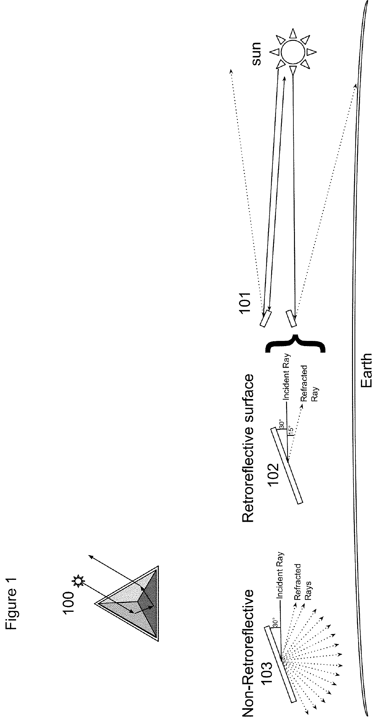
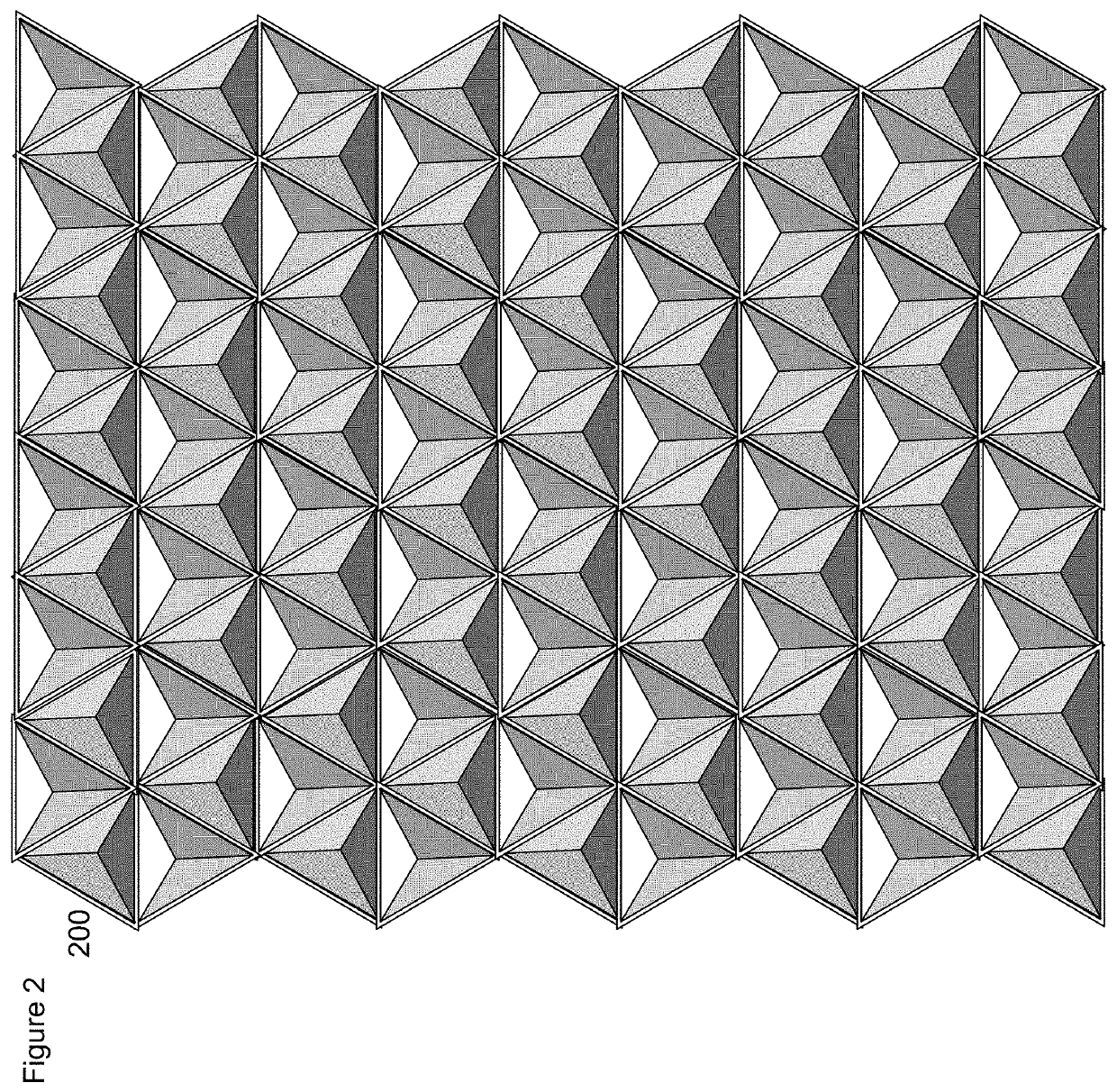
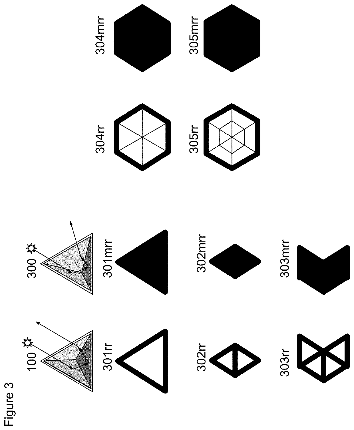
[0035]The current embodiment uses a corner retroreflector to prevent light pollution while preventing undesired absorption on surfaces of an object including the body of the object, solar panels of the object and communication equipment of the object. The use of static modulated retroreflectors (SMRRs) can also be used to label the object so that a remote sensor can identify the object, determine its orientation in space and apply vectors to this orientation. Arrays of Active MRRs (AMRRs) can be used to communicate with remote systems without creating surfaces that create light pollution or absorption. AMRRs can also communicate between multiple sources simultaneously as each light source that hits it will cause it to return the same signal. Arrays of AMRRs can be divided up into banks of AMRR. AMRR banks can all operate in a synchronized way creating a larger signal. This signal can be modulated in amplitude (by adding more AMRRs to the bank) or frequency (by changing the switching...


PUM


Abstract

This patent advances a technique for the use of retroreflectors to prevent light pollution while radiating electromagnetic energy away from an object. As such, the patent defines how to do this on a surface, on a solar panel and with a communication device. It further investigates the communication device and makes it useful for relatively ad-hoc communication systems where aspects of the source and destination locations, distances, orientations and detection equipment is not known ahead of time.

Description

BACKGROUND[0001]One of the simplest Apollo moon experiments has been one of the most successful. A purpose built passive array of mirrors, called retroreflectors, on the moon called the The Lunar Laser Ranging Experiment. The Lunar Laser Ranging Experiment uses no energy and has been giving us exact locations of the moon since Jul. 21, 1969. This patent advances that idea to use an array of retroreflectors to reduce light pollution while reflecting radiant energy away from structures. Non-light polluting retroreflectors then become a way of passively allowing solar panels to reduce albedo, and the creation identification, orientation and communication systems that are also non-light polluting.[0002]Retroreflector: any device or surface that reflects electromagnetic radiation back to its source irrespective of the angle the radiation hits the surface. There are several types of retroreflectors:[0003]A corner retroreflector uses 3 perpendicular reflective surfaces (see image 1).[0004]...

Claims


Application Information

Patent Timeline
IPC IPC(8): H02S40/22F21V7/00F21V14/04
CPCH02S40/22F21V14/04F21V7/0041G02B5/124Y02E10/52
Inventor URRY, DAVID W.
Owner URRY DAVID W
Why Eureka
Try Eureka