Underwater Vehicle with Variable Configuration

a technology of underwater vehicles and configurations, applied in underwater equipment, special-purpose vessels, program-controlled manipulators, etc., can solve the problems of reducing effectiveness and inability to be equally effective in every possible situation, and achieve the effect of improving the strength and speed of manipulating ellipsoids and good local mobility

Active Publication Date: 2021-09-30
UNIVERSITY OF FLORENCE
View PDF0 Cites 1 Cited by
  • Summary
  • Abstract
  • Description
  • Claims
  • Application Information

AI Technical Summary

Benefits of technology

[0021]Object of the present invention is therefore to propose an underwater vehicle with variable configuration having multi-purpose qualities, such as to be able to effectively perform surveillance tasks, such as those carried out by AUVs (Autonomous Underwater Vehicles) with a substantially torpedo shape, rapidly covering also significant distances and, alternatively or additionally, on-site inspection and/or intervention operatio

Problems solved by technology

Due to the elongated torpedo shape, the greater or lesser stability of the hovering vehicle is influenced by how it is oriented with respect to the underwater current by which it is affected, i.e. by how much surface is exposed to said current, and the thrusters, especially since they cannot be steered whil

Method used


Image

  • Underwater Vehicle with Variable Configuration
  • Underwater Vehicle with Variable Configuration
  • Underwater Vehicle with Variable Configuration

Examples


first embodiment

[0044]In the invention, illustrated in FIGS. 1A, 1B, four of the aforementioned elements 20 of the hull 2 are provided, having a torpedo shape, to each of which is associated at least one thruster 3, designed to provide a direct propulsive thrust substantially parallel to the longitudinal axis of the hull 2, in one direction and the opposite one.

[0045]Advantageously, the thrusters 3 are fixed laterally to the elements 20, on the external part with respect to said first closed polygonal structure F1, and are arranged in a fixed position with a thrust axis parallel to the longitudinal axis of the same respective element 20, or in any case with a given angle of inclination with respect to the aforementioned longitudinal axis of the element 20 in the plane identified by the closed polygonal structure F1.

[0046]To each of said joints 21 are associated actuating means 22, schematically illustrated, for example hydraulic or electric, provided for varying and stabilizing a predetermined angl...

second embodiment

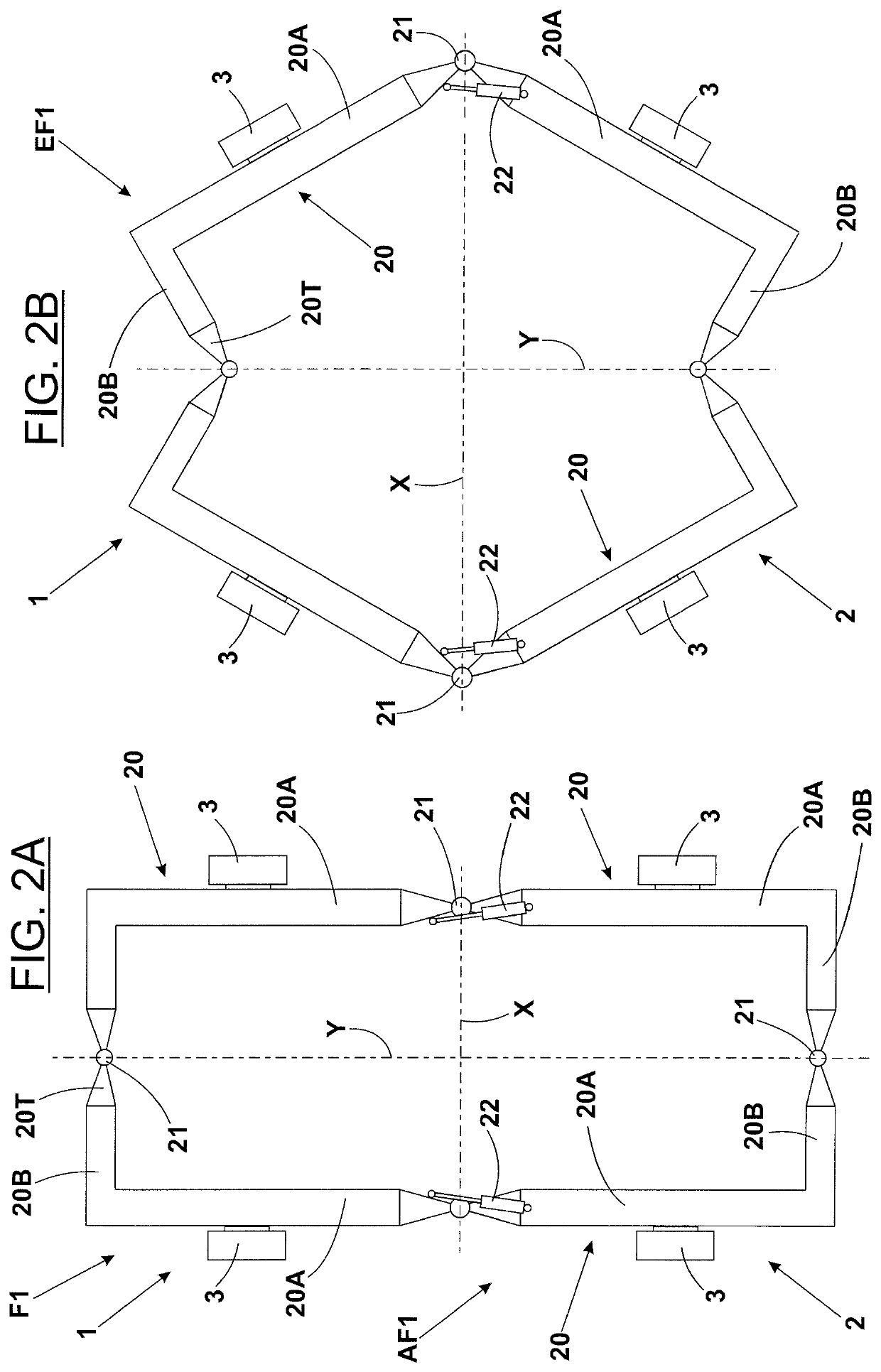
[0051]In the invention, illustrated in FIGS. 2A, B, four elements 20 are still provided to constitute the hull 2, each of which has two consecutive straight portions 20A, 20B, for example arranged at right angle.

[0052]Preferably, the portion 20A of each element 20, to which the relative thruster 3 is associated, has a greater development than the portion 20B.

[0053]The arrangement of the four elements 20, symmetrical with respect to the respective axes X, Y, determines that, in the elongated shape configuration AF1, the hull 2 has a relative first elongated conformation rectangular in shape (FIG. 2A) with the shorter side along the axis X, whereas in the expanded shape configuration EF1, for the same hull 2, it is determined a second conformation, still substantially isotropic, polygonal in shape (FIG. 2B).

[0054]For this second embodiment it is possible to provide only two actuating means 22, associated with the joints 21 arranged on the axis X.

[0055]The thrusters 3 are perfectly par...

fourth embodiment

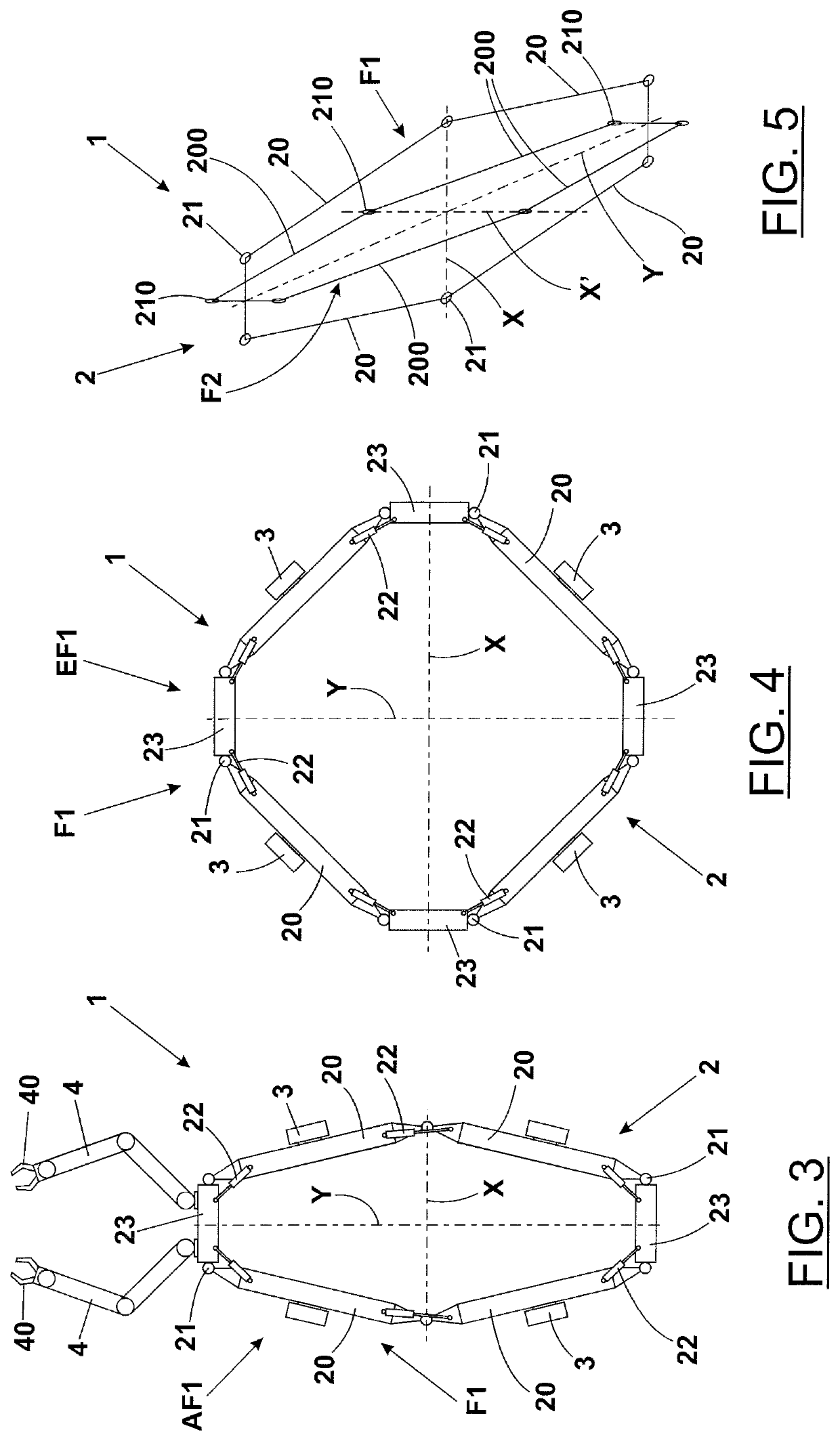
[0061]In the invention, illustrated in FIG. 4 and derived from the third, two further auxiliary supporting elements 23 are provided, interposed between the remaining two elements 20 of the hull 2.

[0062]The further auxiliary supporting elements 23 are connected to the corresponding elements 20 with the interposition of relative joints 21 and actuating means 22, similarly to what stated above.

[0063]Also, for this fourth embodiment, it is provided that at least one of said auxiliary supporting elements 23 is designed to support at least one robotic arm (not shown) equipped with operating tools.

[0064]With said further auxiliary supporting elements 23, the hull 2 has, in the elongated shape configuration AF1, a first elongated conformation octagonal in shape flattened along the transversal axis X, not shown as it is very similar to what shown in FIG. 3, whereas in the expanded shape configuration EF1 the same hull 2 is still with a substantially isotropic conformation, with an octagonal ...


PUM


Abstract

The underwater vehicle with variable configuration (1) comprises: a hull (2) consisting of at least four elongated elements (20), mutually articulated by means of joints (21), to form a first closed polygonal structure (F1), arranged on a plane; thrusters (3), associated in parallel with said elements (20) of the hull (2); actuating means (22), associated with said joints (21), provided for automatically modifying said first closed polygonal structure (F1), from an elongated shape configuration (AF1) to an expanded shape (EF1), corresponding to an elongated conformation of said hull (2), to determine a low hydrodynamic resistance and a longitudinal thrust of the thrusters (3) in the cruising of said underwater vehicle (1), and to a substantially isotropic conformation, wherein the same elements (20) of the hull (2), as well as the thrusters (3) are mutually angled, intended for the hovering of the same underwater vehicle (1), respectively. The latter can be suitably equipped with robotic arms (4) intended for performing maintenance or similar interventions in underwater locations.

Description

TECHNICAL FIELD[0001]The present invention relates to the technical field of underwater vehicles with variable configuration. The invention particularly relates to robotic underwater vehicles with variable configuration, used for surveillance and / or inspection and / or intervention operations not designed to have a driver and / or other staff on board, known as UUV (Unmanned Underwater Vehicles).STATE OF THE ART[0002]Underwater robotic vehicles are constructed with different characteristics depending on the operating needs for which they are intended.[0003]When the purposes are bathymetric survey / surveying or other, where the vehicle is expected to cover significant distances with a good speed, it is useful to have an elongated, e.g. a torpedo-like, conformation offering low hydrodynamic resistance.[0004]According to an acronym known in the field, in this case, they are usually referred to as AUVs (Autonomous Underwater Vehicles), i.e. autonomous vehicles.[0005]On the contrary, when the...

Claims


Application Information

Patent Timeline
IPC IPC(8): B63C11/52B63G8/00B63G8/16
CPCB63C11/52B63G8/001B63B2001/045B63G2008/002B63G8/16B63B2001/145B25J9/08
Inventor ALLOTTA, BENEDETTOGELLI, JONATHANPAGLIAI, MARCORIDOLFI, ALESSANDRO
Owner UNIVERSITY OF FLORENCE
Why Eureka
Try Eureka