

Engine system and engine control method
- Summary
- Abstract
- Description
- Claims
- Application Information
AI Technical Summary
Benefits of technology
Problems solved by technology
Method used
Image

Examples
first embodiment
1>>
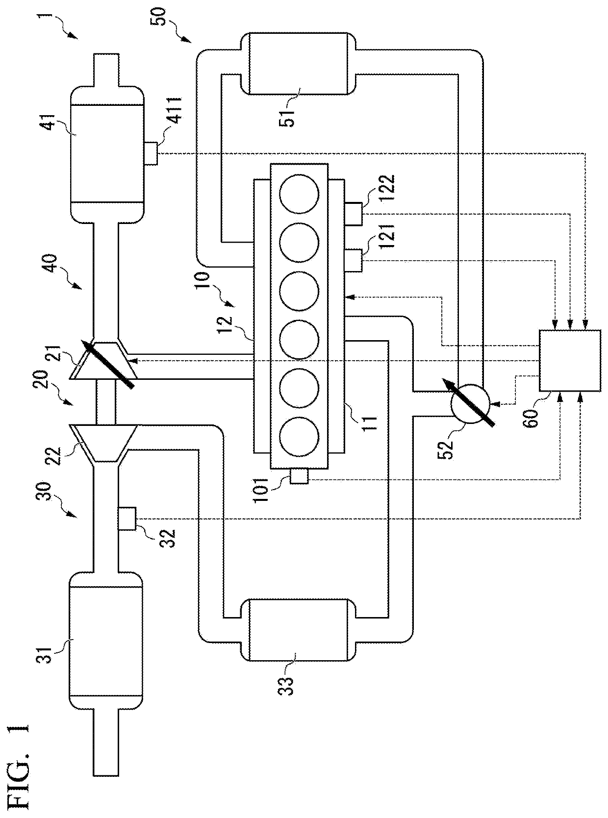
[0024]Hereinafter, embodiments will be described in detail with reference to the drawings. FIG. 1 is a schematic diagram illustrating a configuration of an engine system 1 according to a first embodiment.
[0025]The engine system 1 includes an engine main body 10, a supercharger 20, an intake pipe 30, an exhaust pipe 40, a recirculation pipe 50, and an engine controller 60.
[0026]The engine main body 10 is a diesel engine in which a plurality of combustion chambers are formed. The engine main body 10 is provided with an intake manifold 11 that distributes air to each combustion chamber and an exhaust manifold 12 that collects exhaust gas discharged from each combustion chamber. The engine main body 10 is provided with a rotation speed sensor 101 that measures the rotation speed of the engine main body 10. The intake manifold 11 is provided with a temperature sensor 121 that measures the temperature of the intake manifold 11 and a pressure sensor 122 that measures the pressure of the...
PUM
| Property | Measurement | Unit |
|---|---|---|
| Mass flow rate | aaaaa | aaaaa |
| Mass flow rate | aaaaa | aaaaa |
| Mass flow rate | aaaaa | aaaaa |
Abstract
Description
Claims
Application Information