
Correction method for estimated state-of-charge value of energy storage device, management apparatus for energy storage device, and energy storage apparatus

Pending Publication Date: 2022-09-15
GS YUASA INT LTD
View PDF0 Cites 0 Cited by
  • Summary
  • Abstract
  • Description
  • Claims
  • Application Information

AI Technical Summary

Benefits of technology

The patent text aims to provide a simple understanding of a technical effect. The technical effect of this patent is to improve the efficiency of a heat exchanger by using a special coating on its surfaces. This coating helps to prevent fouling and other contamination, which can reduce the efficiency of the heat exchanger. By using this coating, the heat exchanger is able to maintain its efficiency even after extended use.

Problems solved by technology

The current integration method has a problem that errors (a measurement error of the current sensor, an error caused by an individual difference in a consumption current of a management apparatus that manages the energy storage device, an error caused by an individual difference in the self discharge of the energy storage device, etc.) accumulate as time passes.

Method used


Image

  • Correction method for estimated state-of-charge value of energy storage device, management apparatus for energy storage device, and energy storage apparatus
  • Correction method for estimated state-of-charge value of energy storage device, management apparatus for energy storage device, and energy storage apparatus
  • Correction method for estimated state-of-charge value of energy storage device, management apparatus for energy storage device, and energy storage apparatus

Examples


first embodiment

[0054]A first embodiment will be described with reference to FIGS. 5 to 12. In the following description, reference numerals of the drawings may be omitted for the same constituent members except for some of them.

[0055]A battery 1 (an example of an energy storage apparatus) according to a first embodiment will be described with reference to FIG. 5. An automobile 2 (an example of a vehicle) illustrated in FIG. 5 is an engine automobile and includes a starter for starting an engine. The battery 1 is a battery for starting the engine that is mounted on an automobile 2 and supplies electric power to the starter. The battery 1 is charged by an alternator of the automobile 2 when the engine starts. Although FIG. 5 illustrates a case where the battery 1 is housed in an engine room 2A, the battery 1 may be housed under a floor or in a trunk of a cabin.

[0056](1) Structure of Battery

[0057]As illustrated in FIG. 6, the battery 1 includes an outer case 10 and a plurality of battery cells 12 (an...

second embodiment

[0096]A second embodiment is a modification example of the first embodiment. The battery cell 12 deteriorates with use. Deterioration means that an actual chargeable capacity decreases. Even when the amounts of charged electricity are the same, when the actual capacities are different, appropriate correction values are different. Therefore, in the second embodiment, the correction value is determined in consideration of the degradation of the battery cell 12 in addition to the temperature of the battery cell 12 and the amount of charged electricity. Specifically, the management part 55 according to the second embodiment determines the correction value by Equation 1 below:

Correction value [%]=(actual capacity [Ah] of battery cell 12−eigenvalue [Ah]) / actual capacity [Ah] of battery cell 12×100  .

[0097]In Equation 1, the actual capacity of the battery cell 12 is the present actual capacity of the battery cell 12. The actual capacity of the battery cell 12 can be estimated by an appropr...

third embodiment

[0103]A third embodiment will be described with reference to FIG. 13. A third embodiment is a modification example of the first embodiment or the second embodiment. In FIG. 13, a time point T1 indicates a time point when the engine is started last time, a time point T2 indicates a time point when the engine is stopped last time, a time point T3 indicates a time point when the engine is started this time, and a time point T4 indicates a time point when the battery cell 12 is fully charged after the engine is started this time.

[0104]In the current integration processing 60 according to the third embodiment, the management part 55 further obtains the amount of electricity charged during a period from the start of the engine of the automobile 2 and the start of charge of the battery cell 12 to the stop of the engine in addition to the amount of electricity charged during the period from the start of the engine of the automobile 2 and the start of charge of the battery cell 12 to the ful...


PUM


Abstract

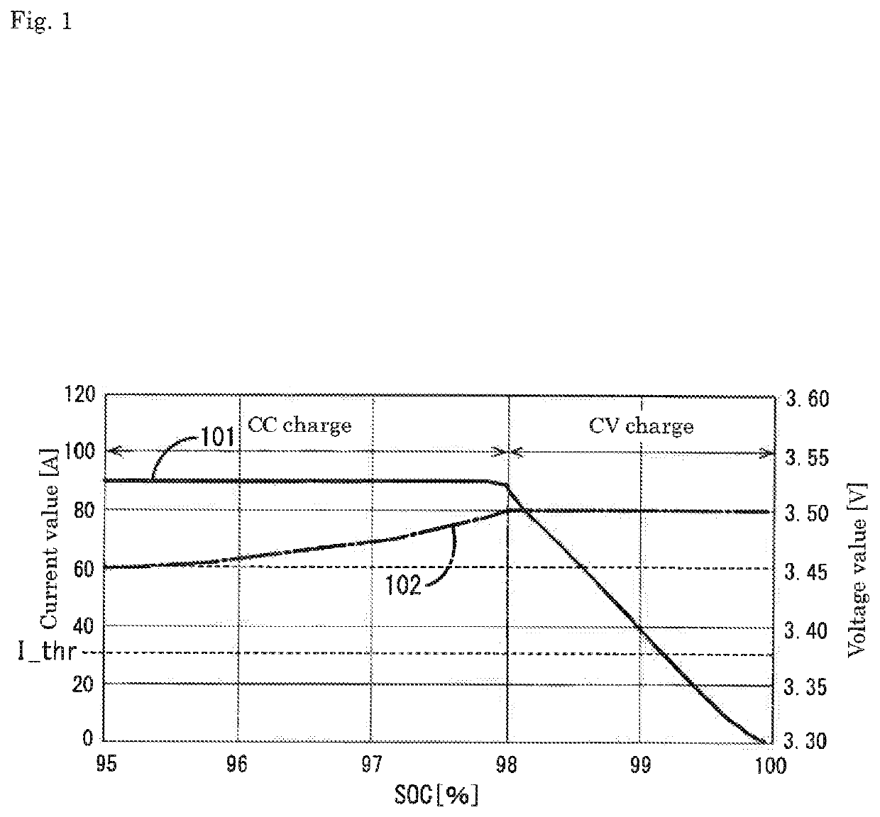
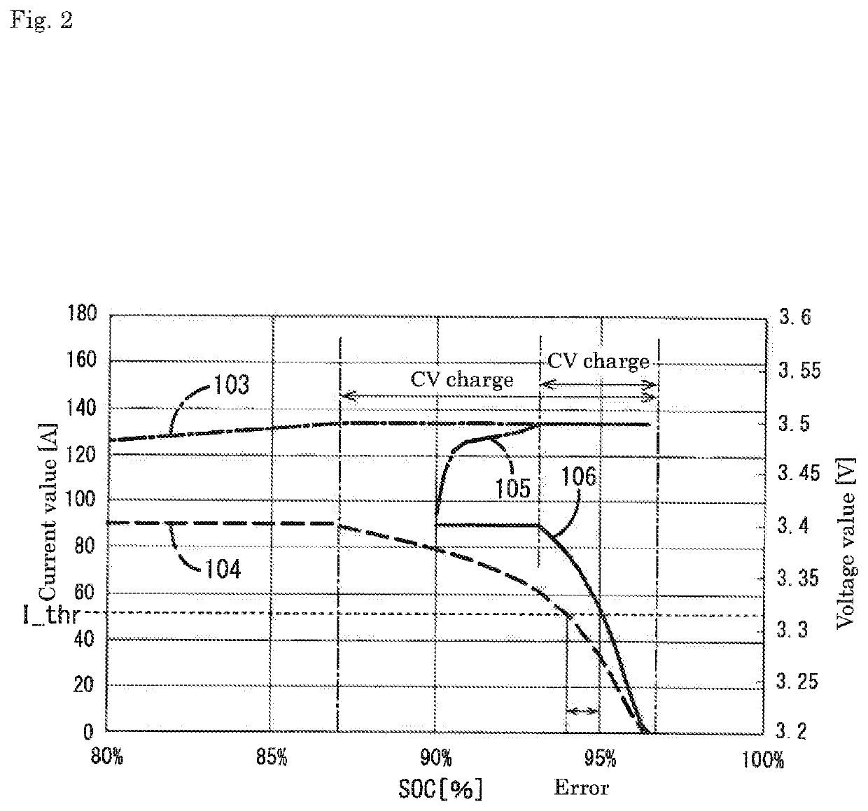
A correction method for an estimated state-of-charge (SOC) value of a battery cell 12 estimated by a current integration method, the method including: a charge step of a battery cell 12; a determination step of determining a correction value of the estimated value based on an amount of electricity charged during a period from a start of charge of the battery cell 12 to a decrease in a current value of a charge current to a predetermined threshold I_thr; and a correction step of correcting the estimated value based on the correction value determined in the determination step.

Description

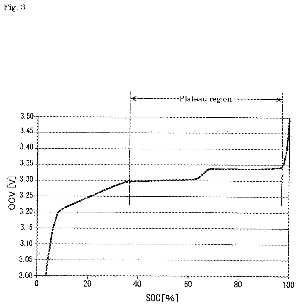
TECHNICAL FIELD[0001]The technology disclosed in the present specification relates to a correction method for an estimated state-of-charge value of an energy storage device, a management apparatus of the energy storage device, and an energy storage apparatus.BACKGROUND ART[0002]As a method for estimating a state of charge (SOC) of an energy storage device such as a lithium ion secondary battery, a current integration method is known. The current integration method is a method in which a current value of a charge-discharge current of an energy storage device is measured at predetermined time intervals with a current sensor, and the SOC [%] is estimated by adding or subtracting the measured current value to or from an initial value.[0003]The current integration method has a problem that errors (a measurement error of the current sensor, an error caused by an individual difference in a consumption current of a management apparatus that manages the energy storage device, an error caused...

Claims


Application Information

Patent Timeline
IPC IPC(8): G01R31/374G01R31/3828H02J7/00H01M10/48H01M10/44
CPCG01R31/374G01R31/3828H02J7/0048H01M10/486H01M10/44H01M2220/20H01M10/48G01R31/006H01M10/443B60R16/04Y02E60/10
Inventor NARIMOTO, SATORUSHIRAISHI, TAKEYUKI
Owner GS YUASA INT LTD
Learn More