Device and Method for Upending a Tubular Element with a Longitudinal Direction at an Outer End

a tubular element and longitudinal direction technology, applied in the direction of machines/engines, final product manufacturing, transportation and packaging, etc., can solve the problems of increasing weight of wind turbine foundations, increasing difficulty in handling, and difficult operation of taking up foundation piles

Pending Publication Date: 2021-09-30
GEOSEA
View PDF3 Cites 3 Cited by
  • Summary
  • Abstract
  • Description
  • Claims
  • Application Information

AI Technical Summary

Benefits of technology

[0008]An object of the present invention is therefore to provide a device and method for upending a tubular element with a longitudinal direction at an outer end, which help to at least partially obviate the above stated prior art drawbacks. The invention particularly seeks to provide an improved device and method for upending a tubular element with a longitudinal direction, particularly a foundation pile of a wind turbine to be placed on an underwater bottom, at an outer end.

Problems solved by technology

Foundations for wind turbines are moreover becoming increasingly heavier because wind turbines are constantly being scaled up.
Because the foundations are becoming increasingly more sizeable, they are increasingly more difficult to handle.
Taking up of a foundation pile is a delicate operation, among other reasons because the foundation pile can easily become damaged herein.
A drawback of the known device is that there is a high chance of damage to a tubular element to be upended, such as a foundation pile.
The known device is also only able to perform its function when the sea is relatively calm, and is generally only suitable for a limited diameter range.

Method used


Image

  • Device and Method for Upending a Tubular Element with a Longitudinal Direction at an Outer End
  • Device and Method for Upending a Tubular Element with a Longitudinal Direction at an Outer End
  • Device and Method for Upending a Tubular Element with a Longitudinal Direction at an Outer End

Examples


Embodiment Construction

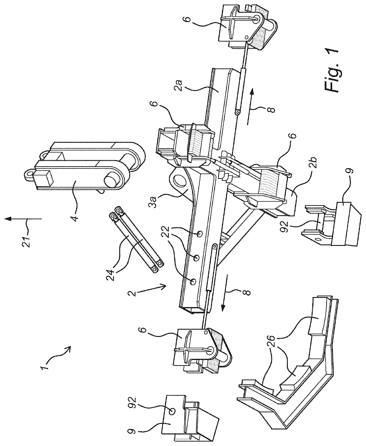
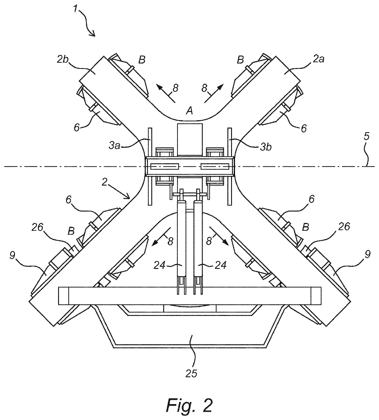
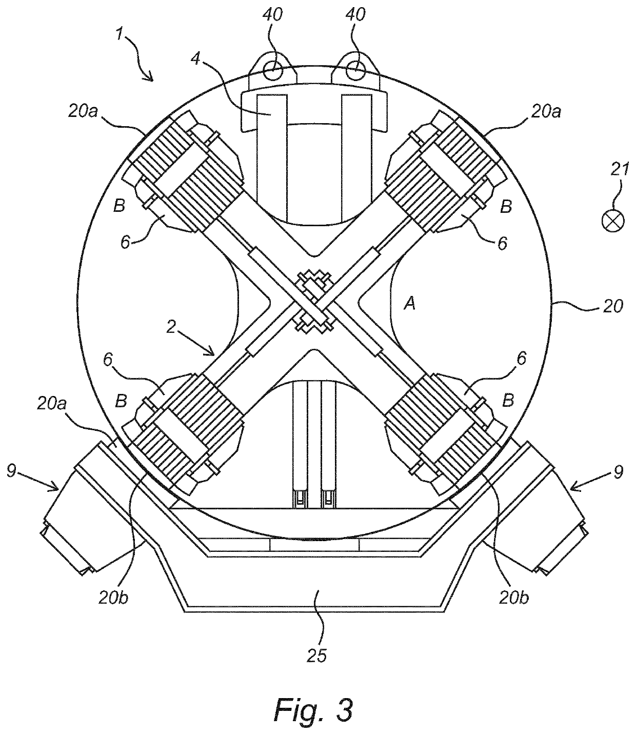
[0048]Referring to the figures, a device 1 for upending a foundation pile 20 with a longitudinal direction at an outer end is shown. Device 1 is likewise suitable for upending and placing other elements with a longitudinal direction, such as for instance transition pieces of a wind turbine mast, optionally on each other or on another surface. In the shown embodiment device 1 comprises a cross-shaped support structure in the form of mutually coupled beams (2a, 2b). The coupling can for instance be brought about by means of welding of beam parts. The beams for instance have a tubular cross-section, although H-beams or I-beams are also possible. In the centre of the cross the support structure is provided with two hinged plates (3a, 3b) in which a lifting member 4 is connected pivotally to support structure 2 by means of a pin-hole connection. Lifting member 4 is provided on a lifting side with lifting eyes 40 for connection to a lifting means such as a crane (not shown), this with int...


PUM


Abstract

Described herein is a device for upending a tubular element with a longitudinal direction at an outer end. The device has a cross-shaped support structure of mutually coupled beams. The support structure is pivotable round a lifting member connected thereto for connection to a lifting means such as a crane. Clamping members slidable along the beams from a clear position to a clamping position can provide for coupling to a wall part of the outer end of the tubular element in the clamping position. In the clamping position the beams extend substantially transversely of the longitudinal direction of the tubular element. Also described herein is a method which makes use of the device.

Description

CROSS-REFERENCE TO RELATED APPLICATIONS[0001]This application is the United States national phase of International Application No. PCT / EP2019 / 069671 filed Jul. 22, 2019, and claims priority to Belgian Patent Application No. 2018 / 5539 filed July 26, 2018, the disclosures of which are hereby incorporated by reference in their entirety.BACKGROUND OF THE INVENTIONField of the Invention[0002]The invention relates to a device and method for upending a tubular element with a longitudinal direction at an outer end. The invention relates particularly to a device and method for upending a foundation pile of a wind turbine to be placed on an underwater bottom and / or a wind turbine tower to be placed on an already installed foundation from a vessel at an outer end. The foundation can here comprise a so-called monopile foundation or a so-called jacket foundation.Description of Related Art[0003]The invention will be elucidated with reference to an offshore wind turbine. This reference does not ho...

Claims


Application Information

Patent Timeline
Patent Type & Authority Applications(United States)
IPC IPC(8): F03D13/10F03D13/25B66C1/10
CPCF03D13/10F03D13/25F05B2240/95F05B2230/61B66C1/108E04H12/345B66C13/08B66C1/54Y02P70/50Y02E10/72B66C1/56Y02E10/727
Inventor RABAUT, DIETER WIM JANVANNIEUWENHUYSE, KENNETH GERARDMICHIELSEN, JAN MARIA KOEN
Owner GEOSEA
Why Eureka
Try Eureka