Electronic system, die assembly and device die

Active Publication Date: 2021-10-14
NAN YA TECH
View PDF3 Cites 0 Cited by
  • Summary
  • Abstract
  • Description
  • Claims
  • Application Information

AI Technical Summary

Benefits of technology

[0024]With the above-mentioned configurations of the device die having the transfer pad separated into the plurality of segments, the w

Problems solved by technology

However, there are many ch

Method used


Image

  • Electronic system, die assembly and device die
  • Electronic system, die assembly and device die
  • Electronic system, die assembly and device die

Examples


Example

[0038]Embodiments, or examples, of the disclosure illustrated in the drawings are now described using specific language. It shall be understood that no limitation of the scope of the disclosure is hereby intended. Any alteration or modification of the described embodiments, and any further applications of principles described in this document, are to be considered as normally occurring to one of ordinary skill in the art to which the disclosure relates. Reference numerals may be repeated throughout the embodiments, but this does not necessarily mean that feature(s) of one embodiment apply to another embodiment, even if they share the same reference numeral.

[0039]It shall be understood that, although the terms first, second, third, etc. may be used herein to describe various elements, components, regions, layers or sections, these elements, components, regions, layers or sections are not limited by these terms. Rather, these terms are merely used to distinguish one element, component...


PUM


Abstract

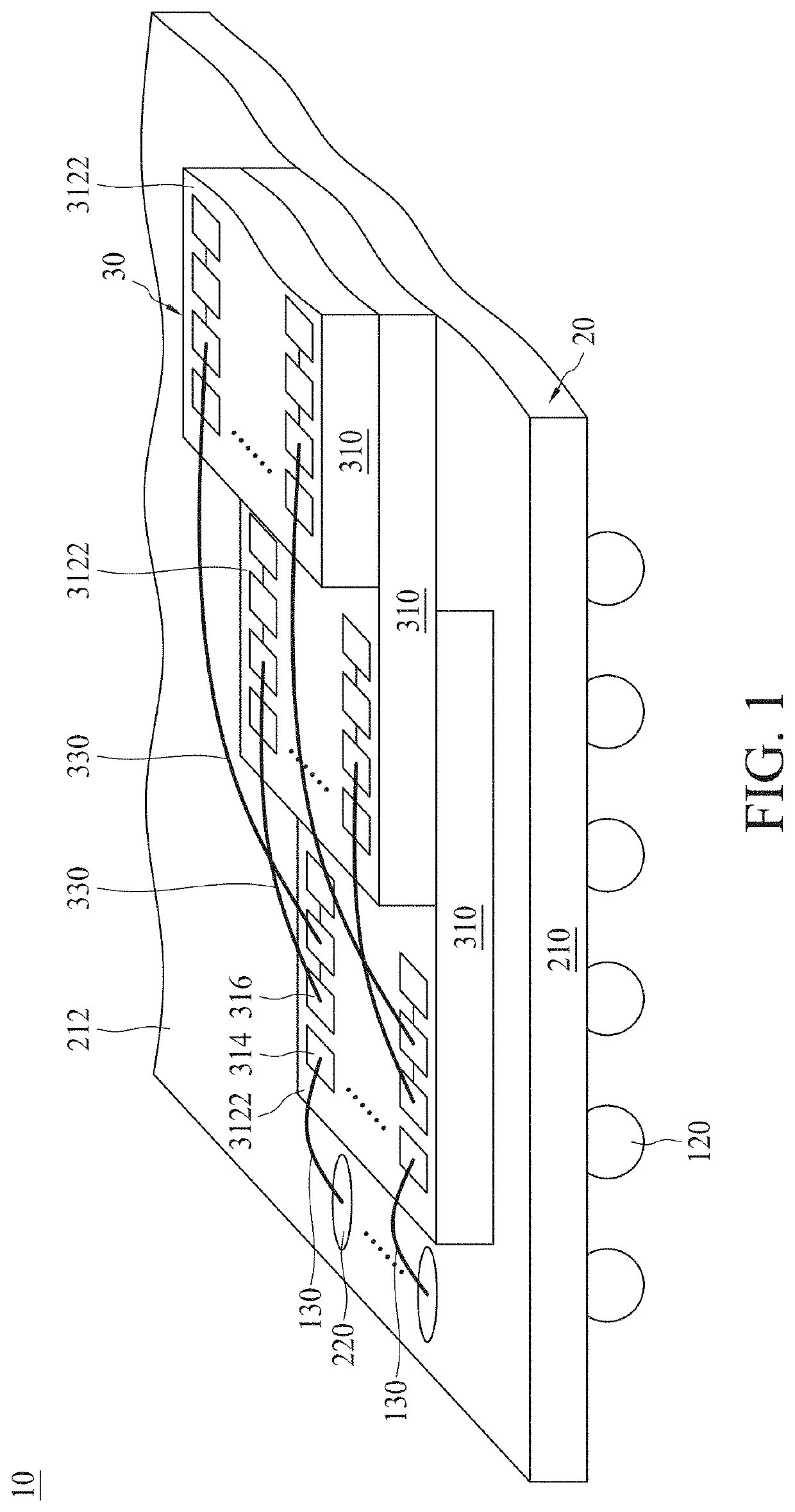
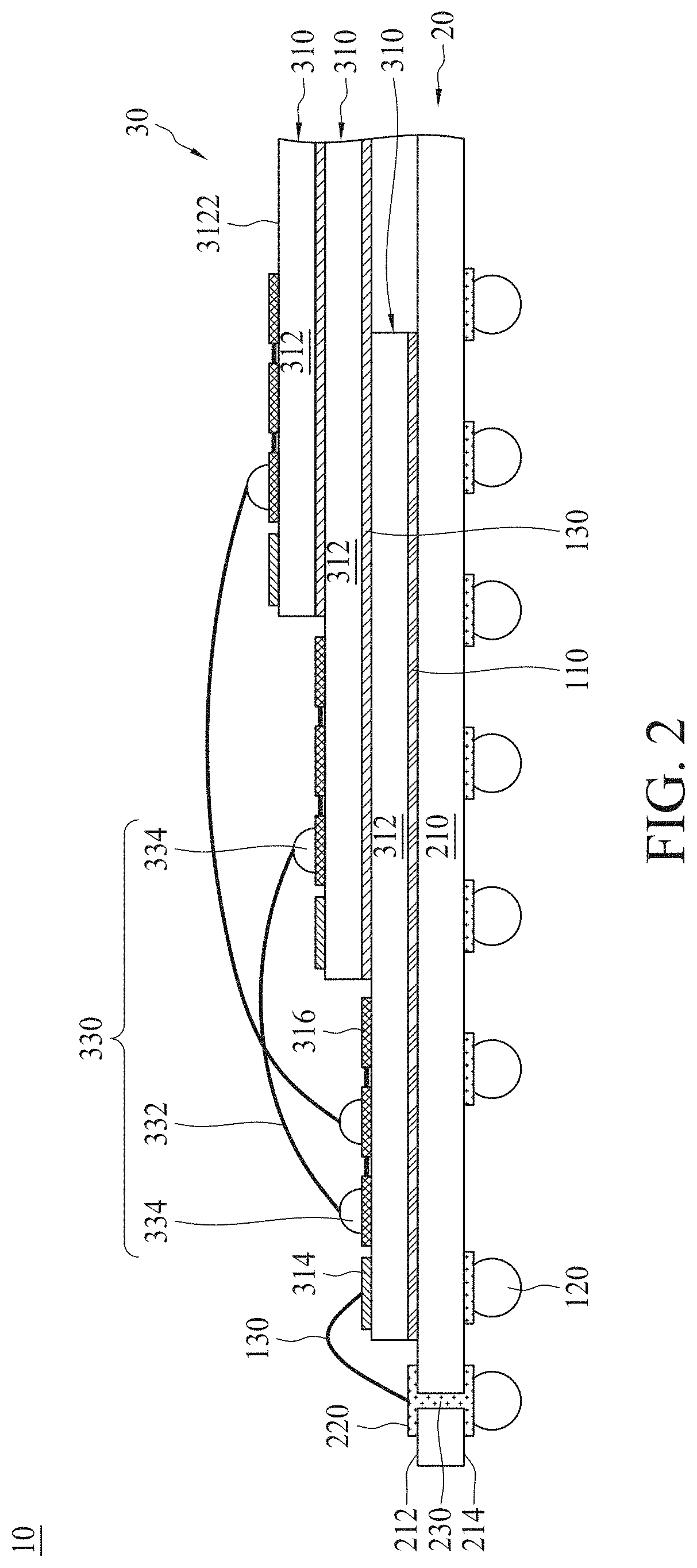
The present disclosure provides a device die, a die assembly and an electronic system. The device die includes a package and a plurality of transfer pads disposed on a functional surface of the package. The transfer pads are divided into a plurality of segments electrically isolated from each other. In an adjacent pair of transfer pads, there is only one electrical connection between the transfer pads, comprising one segment in one transfer pad electrically connected to one segment in the other transfer pad. The die assembly includes a pair of device dies stacked in a stepped configuration. The electronic system includes a supporting member having at least one metallic layer, and a plurality of device dies disposed on the supporting member and mechanically and electrically coupled to the metallic layer by a plurality of conductive strings.

Description

TECHNICAL FIELD[0001]The present disclosure relates to a device die, a die assembly and an electronic system, and more particularly, to a device die having an interconnection structure in which wiring capacitance is effectively reduced, a three-dimensional (3D) die assembly including the device die to improve signal transmission speed, and an electronic device including the die assembly.DISCUSSION OF THE BACKGROUND[0002]Semiconductor devices are used in a variety of electronic applications, such as personal computers, cell phones, digital cameras, and other electronic equipment. Semiconductor devices are typically fabricated by sequentially depositing insulating or dielectric layers, conductive layers, and semiconductive layers of material over a semiconductor substrate, and patterning the various material layers using lithography to form circuit components and elements thereon. Many integrated circuits are typically manufactured on a single semiconductor wafer, and individual dies ...

Claims


Application Information

Patent Timeline
IPC IPC(8): H01L25/065H01L23/00
CPCH01L25/0657H01L24/05H01L24/13H01L24/45H01L24/29H01L25/18H01L23/4824H01L24/48H01L23/49816H01L2224/48091H01L2224/48149H01L2224/48159H01L2225/06562H01L2225/06568H01L2225/0651H01L2225/06506H01L2224/48227H01L2224/48145H01L2224/85444H01L2224/85447H01L2224/85424H01L2224/73265H01L2924/15311H01L2224/32145H01L2224/32225H01L2224/83101H01L2224/8385H01L2224/2919H01L2924/00014H01L2224/48235H01L24/06H01L2224/06138H01L24/32H01L24/73H01L2224/48464H01L2224/83191H01L24/92H01L2224/92247H01L24/83H01L2224/0613H01L2224/04042H01L24/85H01L2924/181H01L2224/45147H01L2224/051H01L2224/45124H01L2224/45144H01L2924/00012H01L2924/0665H01L2224/45099H01L2924/013H01L2924/07025
Inventor YANG, WU-DER
Owner NAN YA TECH
Why Eureka
Try Eureka