
Hybrid sensor system and method for providing 3D imaging

a sensor system and hybrid technology, applied in the field of hybrid sensor systems and methods for providing 3d imaging, can solve the problems of adversely affecting resolution, detection range, speed and/or stability, difficult to meet the demands, and difficult to provide high resolution and high quality 3d depth information for adas and autonomous driving applications

Active Publication Date: 2021-10-21
SAMSUNG ELECTRONICS CO LTD
View PDF5 Cites 8 Cited by
  • Summary
  • Abstract
  • Description
  • Claims
  • Application Information

AI Technical Summary

Benefits of technology

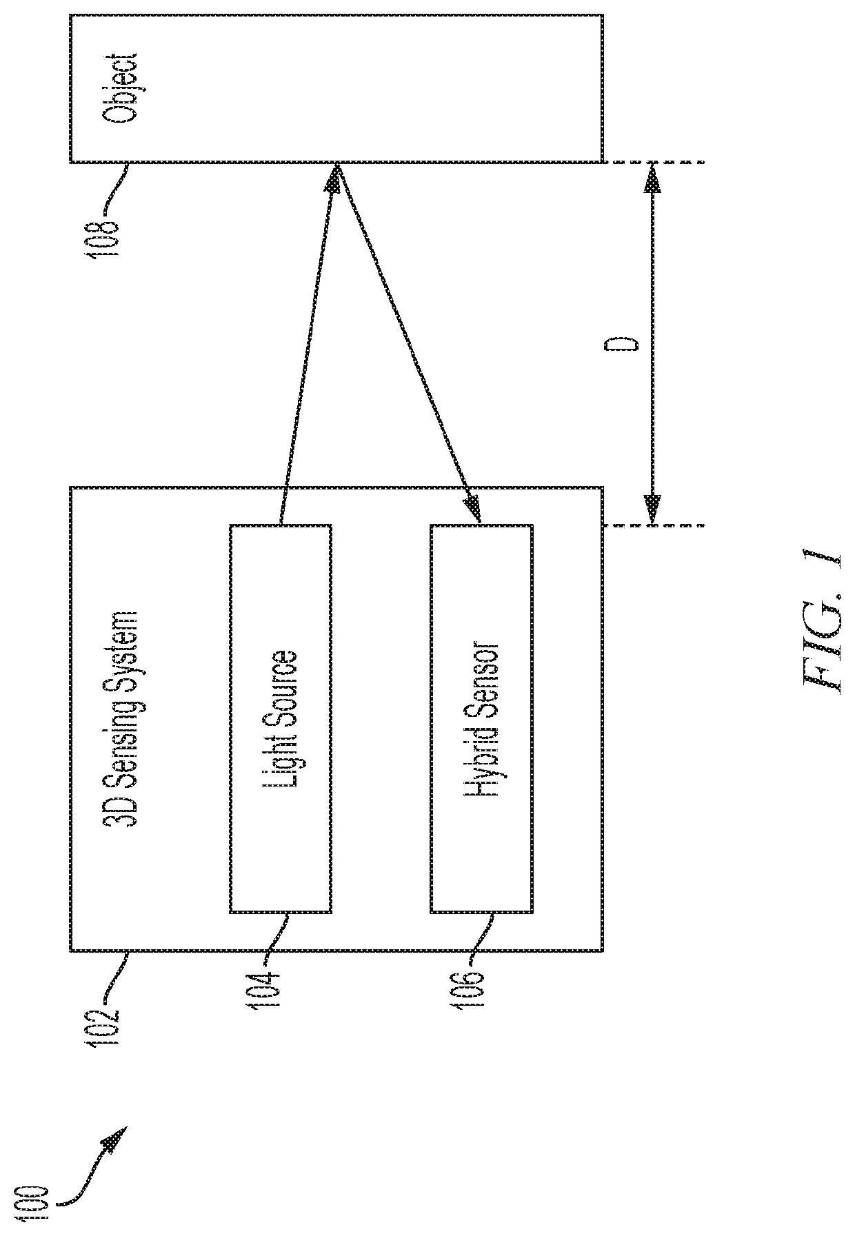
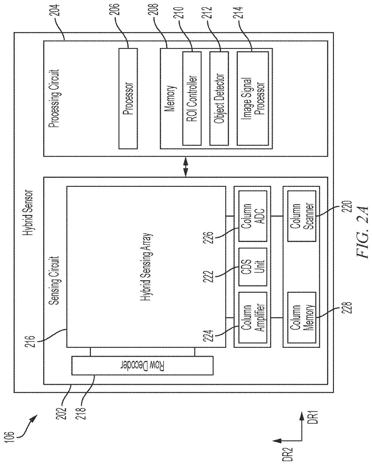
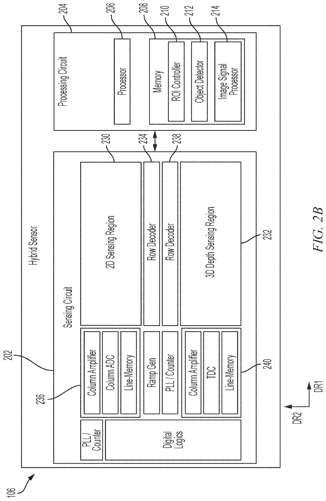
The present patent is about a system and method for 3D imaging using a hybrid sensing array that detects both ambient light and light emitted by a light source. The system includes a metalens that directs light from the light source and the ambient light reflected from the object towards the 2D sensing region and the 3D depth sensing region. The processing circuit combines the 2D image information and the 3D depth information to generate a combined 3D image. The technical effects of this system include improved image quality and faster processing.

Problems solved by technology

However, it can be difficult to meet the demands of ADAS, autonomous driving applications, AR, VR, and the like due to hardware and software limitations which may adversely impact resolution, detection range, speed, and / or stability.
For example, it can be challenging to provide high resolution and high quality 3D depth information for ADAS and autonomous driving applications.
However, translating the data from these separate detection systems into a high quality 3D image may be difficult.
Moreover, misalignment or inability to align corresponding points between 2D image data and 3D depth data may undermine the effectiveness of the separate systems for computer vision applications.

Method used


Image

  • Hybrid sensor system and method for providing 3D imaging
  • Hybrid sensor system and method for providing 3D imaging
  • Hybrid sensor system and method for providing 3D imaging

Examples


Embodiment Construction

[0041]Hereinafter, example embodiments will be described in more detail with reference to the accompanying drawings, in which like reference numbers refer to like elements throughout. The present disclosure, however, may be embodied in various different forms, and should not be construed as being limited to only the illustrated embodiments herein. Rather, these embodiments are provided as examples so that this disclosure will be thorough and complete, and will fully convey the aspects and features of the present disclosure to those skilled in the art. Accordingly, processes, elements, and techniques that are not necessary to those having ordinary skill in the art for a complete understanding of the aspects and features of the present disclosure may not be described. Unless otherwise noted, like reference numerals denote like elements throughout the attached drawings and the written description, and thus, descriptions thereof may not be repeated.

[0042]Generally, LiDAR systems, for ex...


PUM


Abstract

Provided is a 3D depth sensing system and method of providing an image based on a hybrid sensing array. The 3D sensing system including a light source configured to emit light, a hybrid sensing array comprising a 2D sensing region configured to detect ambient light reflected from an object and a 3D depth sensing region configured to detect the light emitted by the light source and reflected from the object, a metalens on the hybrid sensing array, the metalens being configured to direct the ambient light reflected from the object towards the 2D sensing region, and to direct the light emitted by the light source and reflected from the object towards the 3D depth sensing region, and a processing circuit configured to combine 2D image information provided by the 2D sensing region and 3D information provided by the 3D depth sensing region to generate a combined 3D image.

Description

CROSS-REFERENCE TO RELATED APPLICATION[0001]This application claims priority to and the benefit of U.S. Provisional Application No. 63 / 012,000, filed on Apr. 17, 2020, entitled “A hybrid photodiode and SPAD array and sensor system to improve 3D depth information,” the entire content of which is incorporated by reference herein.BACKGROUND1. Field[0002]Aspects of one or more embodiments of the present disclosure relate to a hybrid sensor system and method for 3D imaging.2. Description of the Related Art[0003]In recent years, applications that rely on computer vision such as advanced driver assistance systems (“ADAS”), autonomous driving applications, augmented reality (“AR”), virtual reality (“VR”), and the like have become more widely demanded. Different detection systems such as Light Detection and Ranging (“LiDAR”), cameras, and the like have been provided to support ADAS, autonomous driving applications, AR, VR, and the like. Such detection systems provide information to assist th...

Claims


Application Information

Patent Timeline
IPC IPC(8): G01S17/894H04N13/254H04N13/156H04N5/369G06K9/00G06T7/20G06T7/521G06T7/55
CPCG01S17/894H04N13/254H04N13/156H04N5/379G05D1/0088G06K9/00201G06T7/20G06T7/521G06T7/55H04N5/36965H04N13/204H04N13/271H04N13/293G01S17/86G01S17/10G01S17/931G01S7/4816H04N13/236H04N13/275H04N25/705H04N25/75G05D1/0246G06T2207/10028G06T2207/30252G06V20/64H04N25/79H04N13/25G03B35/08G03B35/10
Inventor KIM, KWANG OHWANG, YIBING MICHELLESIDDIQUE, RADWANUL HASANSHI, LILONGWANG, CHUNJI
Owner SAMSUNG ELECTRONICS CO LTD
Learn More