
Device for generating a variable angular momentum, in particular for spacecraft attitude control

a technology of generating a variable angular momentum and generating a generator, which is applied in the direction of generator/motor, magnetic circuit characterised by magnetic materials, magnetic circuit shape/form/construction, etc. it can solve the problems of high manufacturing cost of mechanical swirl and reaction wheels, limited lifetime, and easy failure of mechanical systems. , to achieve the effect of reversing the angular momentum, simple, reliable and cost-effective, and distinctly less wear

Pending Publication Date: 2021-10-28
UNIV STUTTGART
View PDF9 Cites 0 Cited by
  • Summary
  • Abstract
  • Description
  • Claims
  • Application Information

AI Technical Summary

Benefits of technology

The patent describes a device that uses magnetic field to generate a torque and control the position and orientation of a spacecraft or robot arm without needing mechanical components or external magnetic fields. The device generates a rotating or wandering magnetic field that magnetizes the fluid inside a container and moves it on a closed orbit inside the container. By controlling the speed at which the magnetic field rotates or moves, the device can vary the speed of movement and generate torque. This technology can be simple, reliable, and cost-effective, and can be used for spacecraft attitude control and other applications where a variable angular momentum is needed.

Problems solved by technology

However, mechanical swirl and reaction wheels are very expensive to manufacture, since very high requirements are placed on tolerances and concentricity properties.
Such mechanical systems can also easily fail, and only have a limited lifetime.
A propulsion system for generating the angular momentum consumes fuel, and is thus only limitedly available.
The fuel mass additionally increases the start costs of the spacecraft.
A propulsion system often only offers limited possibilities for high-precision attitude control.
In this embodiment, however, the ferrofluid is only transported from one respective magnet to the next, and there decelerated again by the magnets, so that a large enough angular momentum cannot be generated.

Method used


Image

  • Device for generating a variable angular momentum, in particular for spacecraft attitude control
  • Device for generating a variable angular momentum, in particular for spacecraft attitude control

Examples


Embodiment Construction

[0006]The object is achieved with the device according to claim 1. Advantageous embodiments of the device are the subject of the dependent claims, or can be derived from the following description as well as the exemplary embodiments.

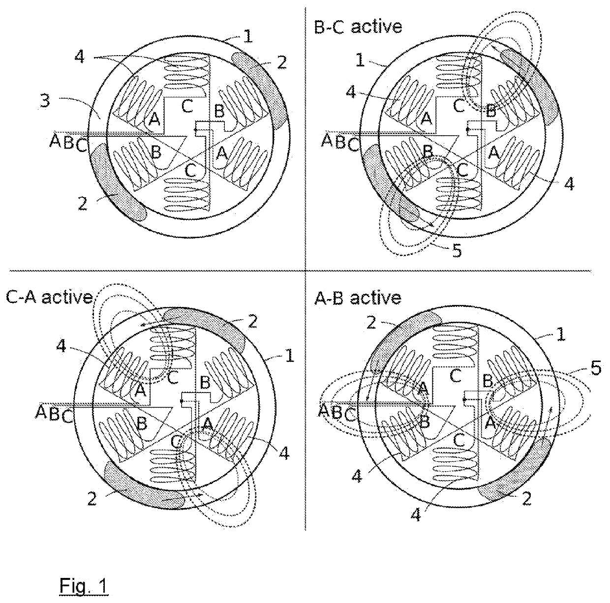
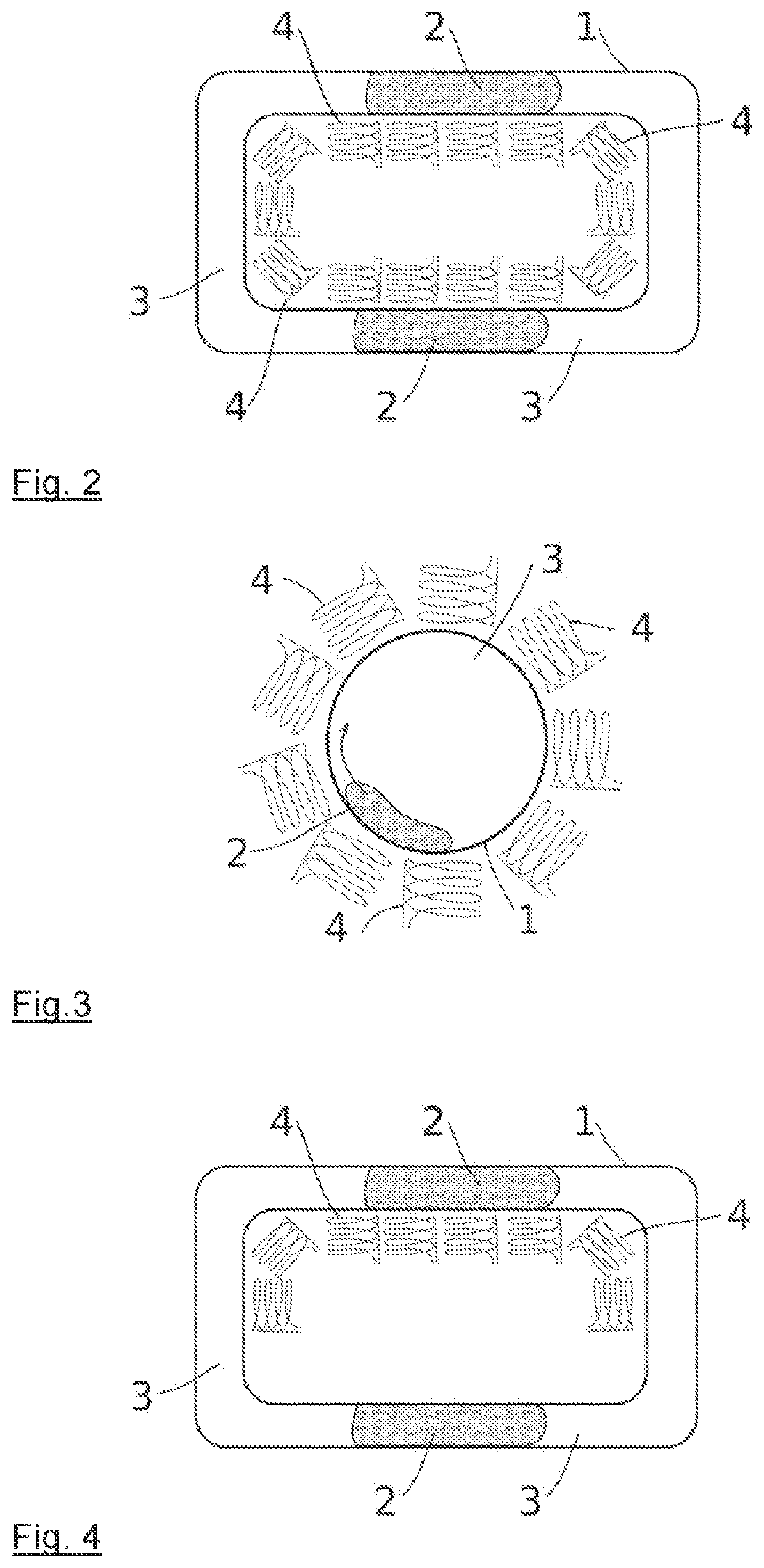
[0007]The proposed device has a container that is only partially filled with a magnetizable fluid, in particular a ferrofluid, and a device for generating one or several rotating or wandering magnetic fields, with which the magnetizable fluid in the container can be made to continuously move on a closed path. The remaining interior volume of the container only partially filled with the magnetizable fluid is filled up with a gaseous medium, e.g., air, or a liquid medium, which does not mix with the magnetizable fluid. The device for generating the one or the several rotating or wandering magnetic fields has several electric coils for generating the magnetic fields, whose coil axes lie in the orbital plane of the closed movement path of the magnetizable fl...


PUM


Abstract

The present invention relates to a device for generating a variable angular momentum or torque, which has a container (1) partially filled with a magnetizable fluid (2) and a device for generating one or several rotating or wandering magnetic fields, with which the magnetizable fluid (2) in the container (1) can be made to continuously move on a closed orbit. The device for generating the rotating or wandering magnetic fields has several electric coils (4), whose coil axes lie in the orbital plane. This structure makes it possible to generate a variable angular momentum without mechanical moved parts or the necessity of external magnetic fields. For example, the device enables a simple and cost-effective spacecraft attitude control.

Description

TECHNICAL FIELD OF APPLICATION[0001]The present invention relates to a device for generating a variable angular momentum, which has a container partially filled with a magnetizable fluid and a device for generating at least one rotating magnetic field, with which the magnetizable fluid in the container can be made to continuously move on a closed orbit. For example, such a device can be used for spacecraft attitude control.PRIOR ART[0002]During the operation of spacecraft, it is often necessary to provide one or several devices on the spacecraft with which the position of the spacecraft can be specifically changed or corrected. For example, this can take place via a propulsion system of the aircraft, which generates an angular momentum by way of an eccentric thrust. It is further known to equip spacecraft with mechanical swirl and reaction wheels. An angular momentum is here stored in a rapidly rotating flywheel, and transferred to the spacecraft when needed by accelerating or decel...

Claims


Application Information

Patent Timeline
IPC IPC(8): B64G1/24B64G1/28
CPCB64G1/244B64G1/28H02K44/00H02K1/02H02K7/14H02K2213/03H02K99/20H02N11/006H02N11/008H02K1/12
Inventor EHRESMANN, MANFREDHERDRICH, GEORG HEINRICHFASOULAS, STEFANOS
Owner UNIV STUTTGART
Learn More