Manufacturing method of iron core, iron core, and stator

a technology of iron core and stator, which is applied in the manufacture of stator/rotor body, magnetic circuit characterised by magnetic materials, and shape/form/construction of magnetic circuits, etc. it can solve the problems of reducing material yield, affecting the connection body thickness of the iron core piece, and largely wasted metal plate materials. achieve excellent magnetic properties, high material yield, and high productivity

Inactive Publication Date: 2021-10-28
PANASONIC INTELLECTUAL PROPERTY MANAGEMENT CO LTD
View PDF5 Cites 0 Cited by
  • Summary
  • Abstract
  • Description
  • Claims
  • Application Information

AI Technical Summary

Benefits of technology

[0016]According to the present disclosure, it is possible to provide the manufacturing method of the iron core, the iron core, a...

Problems solved by technology

Therefore, when the iron core piece is formed by punching the metal plate, a material of the metal plate is largely wasted, and a material yield is decreased.
However, according to the method disclosed in Japanese Patent Unexamined Publication No. 1-264548, when a connection portion is bent and plastically deformed, a plate thickness of an iron core piece connection body is changed (for example, swelling).
That is, according to the method disclosed in Japanese Patent Unexamined Publication No. 1-264548, the connection portion cannot be accurately bent, and the iron core pi...

Method used


Image

  • Manufacturing method of iron core, iron core, and stator
  • Manufacturing method of iron core, iron core, and stator
  • Manufacturing method of iron core, iron core, and stator

Examples


exemplary embodiment 1

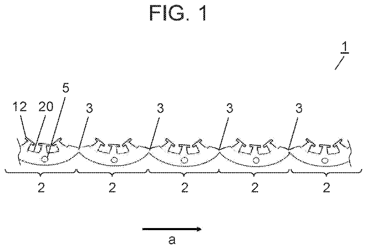
[0043]Hereinafter, continuous iron core piece 1 of Exemplary embodiment 1 will be described with reference to FIG. 1. FIG. 1 is a top view of continuous iron core piece 1.

[0044]As illustrated in FIG. 1, continuous iron core piece 1 of Exemplary embodiment 1 is a member in which a plurality of iron core pieces 2 are connected in a strip shape. Continuous iron core piece 1 is formed by performing press punching on a soft magnetic steel plate having a strip shape. Each iron core piece 2 has a substantially fan shape (including a fan shape) in a top view. Arrow a in FIG. 1 indicates a traveling direction of the press punching (in other words, a longitudinal direction of continuous iron core piece 1). The plurality of iron core pieces 2 have the same size and the same shape. Iron core piece 2 has tooth portion 12 and yoke portion 20. One through-hole 5 is formed in yoke portion 20. As an example, FIG. 1 illustrates a case where the number of through-holes 5 is one. However, the present d...

exemplary embodiment 2

[0077]Hereinafter, continuous iron core piece 21 of Exemplary embodiment 2 will be described with reference to FIG. 7. FIG. 7 is a top view of continuous iron core piece 21.

[0078]As illustrated in FIG. 7, continuous iron core piece 21 is a member in which a plurality of iron core pieces 22 are connected to each other in a strip shape. Continuous iron core piece 21 is formed by performing press punching on a soft magnetic steel plate having a strip shape. Each iron core piece 22 has a substantially circular shape (including a circular shape) in a top view. Arrow a in FIG. 7 indicates a traveling direction of press punching (in other words, a longitudinal direction of continuous iron core piece 21).

[0079]The plurality of iron core pieces 22 have the same size and the same shape. Iron core piece 22 has tooth portion 12 and yoke portion 20. Four through-holes 5 are formed in yoke portion 20. As an example, FIG. 7 illustrates a case where the number of through-holes 5 is four. However, t...

exemplary embodiment 3

[0104]Hereinafter, a manufacturing method of split iron core 35 according to Exemplary embodiment 3 will be described with reference to FIGS. 10A, 10B, 11A, 11B, 12A, and 12B.

[0105]FIGS. 10A, 11A, and 12A are top views of split iron core 35. FIGS. 10B, 11B, and 12B are side views of split iron core 35.

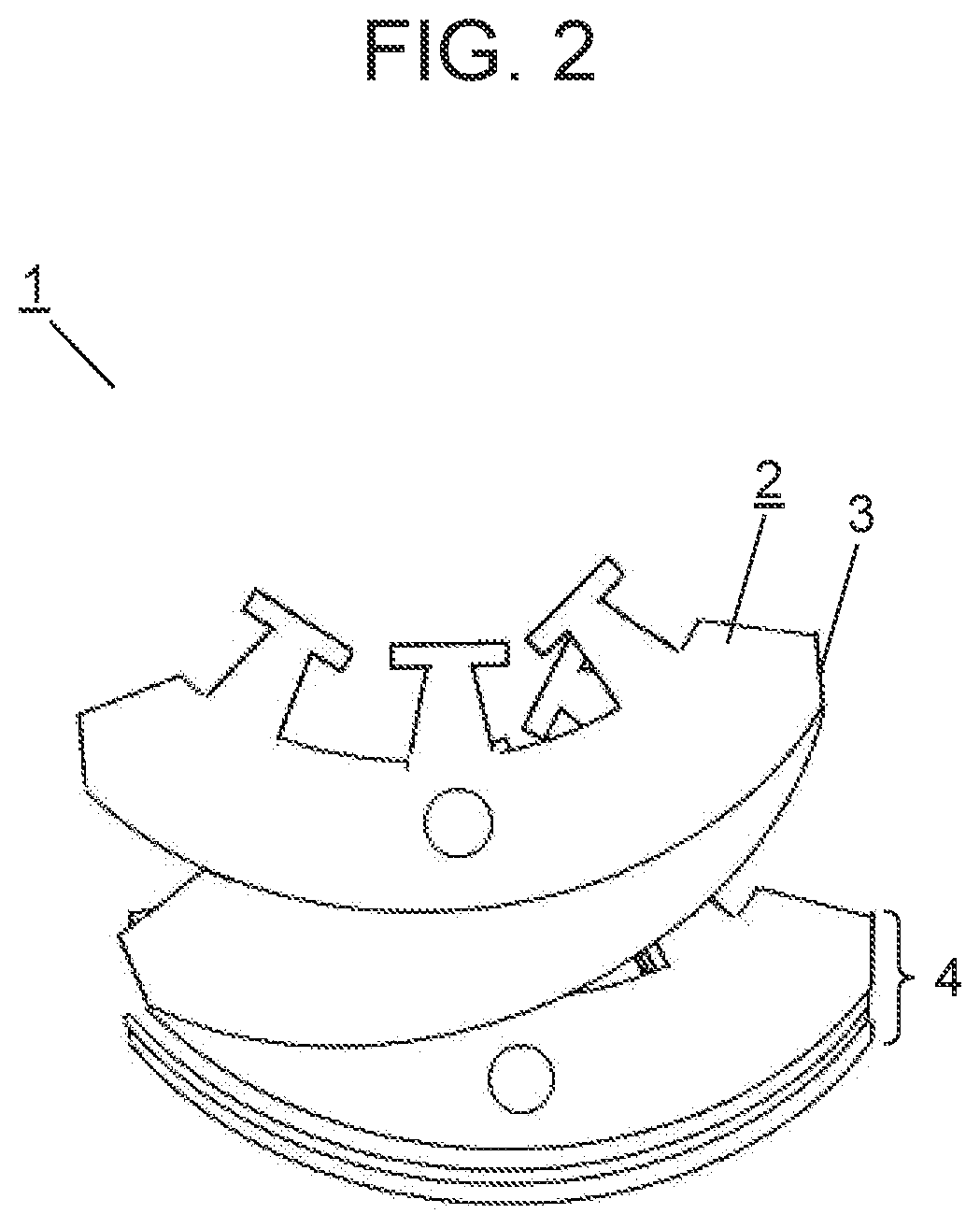
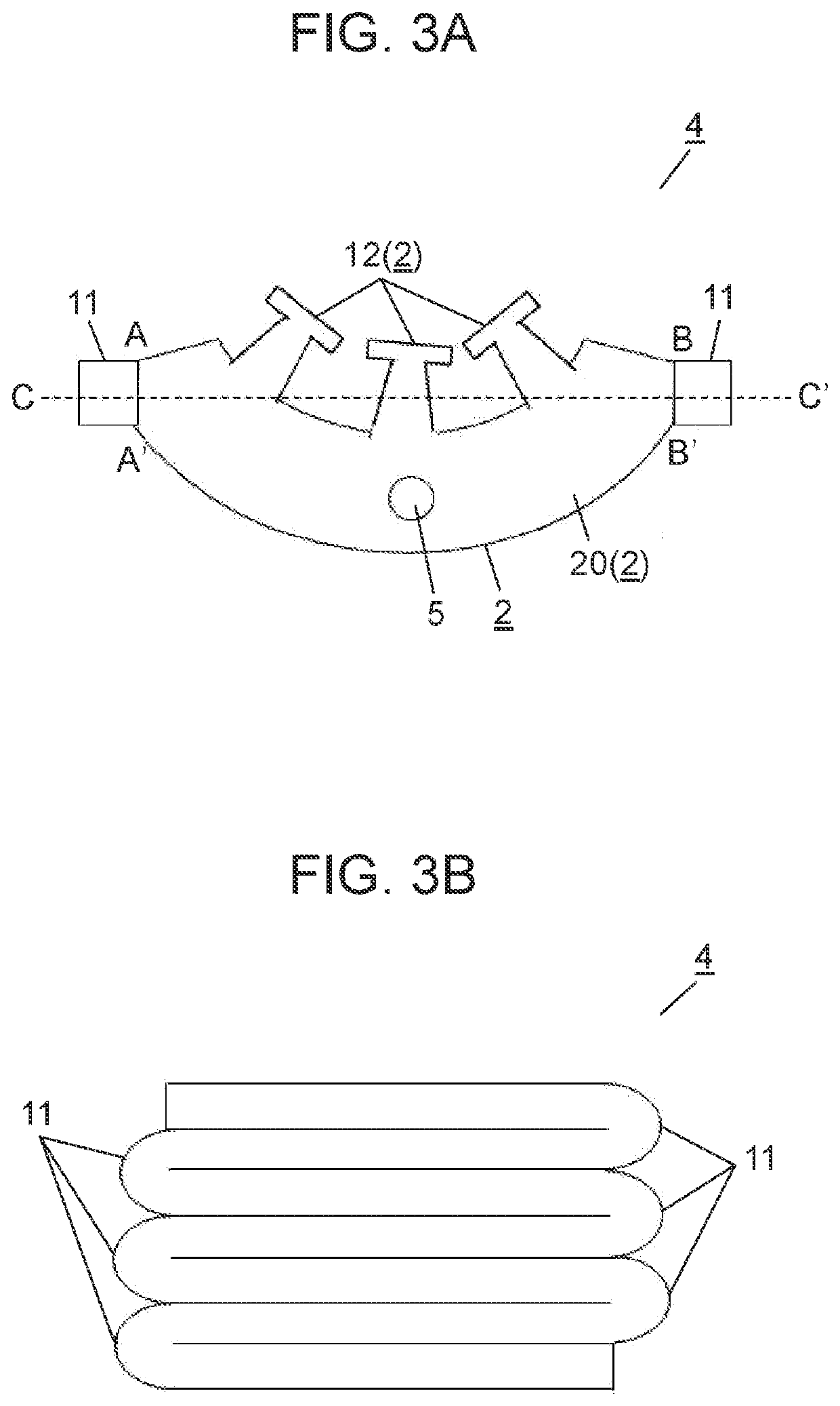
[0106]Here, as illustrated in FIGS. 10A and 10B, split iron core 35 of Exemplary embodiment 3 is manufactured by using continuous iron core piece 1 (refer to FIG. 1) described in Exemplary embodiment 1 and laminated body 4 (refer to FIGS. 3A and 3B) manufactured by using continuous core piece 1. However, as illustrated in FIG. 10A, coil 13 is not provided in split iron core 35 when laminated body 4 is manufactured.

[0107]A step of manufacturing split iron core 35 in a state illustrated in FIGS. 10A and 10B is the same as that of Exemplary embodiment 1 except for a step of winding coil 13 around tooth portion 12. Accordingly, description thereof will be omitted here.

[0108]That is, in Exe...


PUM


Abstract

A manufacturing method of manufacturing an iron core includes connecting a plurality of iron core pieces each including a tooth portion and a yoke portion in a strip shape, connecting the iron core pieces adjacent to each other by a connection portion, and forming a continuous iron core piece provided line-symmetrically with reference to the connection portion. A laminated body is formed by bending and superimposing the iron core pieces adjacent to each other while the connection portion is used as a symmetry axis. A pressure is applied in a laminating direction of the laminated body to fix the laminated body, and a coil is provided in the tooth portion. In this manner, it is possible to realize a manufacturing method of an iron core, which have a high material yield, high productivity, and excellent magnetic properties by using a thin iron core piece.

Description

BACKGROUND1. Technical Field[0001]The present disclosure relates to a manufacturing method of an iron core, an iron core, and a stator.2. Description of the Related Art[0002]In the related art, an iron core (also referred to as a stator core) used for a stator of a motor is formed as follows. A metal plate is first punched by using a press mold device to form a plurality of iron core pieces. The formed iron core pieces are laminated and caulked and joined to each other to manufacture the iron core.[0003]According to the manufacturing method of the above-described iron core, the iron core having a satisfactorily accurate shape can be manufactured. On the other hand, each of the iron core pieces configuring the iron core has an annular shape having an opening portion for accommodating a rotor in a center. Therefore, when the iron core piece is formed by punching the metal plate, a material of the metal plate is largely wasted, and a material yield is decreased.[0004]As a method for el...

Claims


Application Information

Patent Timeline
IPC IPC(8): H02K15/02H02K1/14
CPCH02K15/022H02K1/146H02K15/02H02K1/02H02K1/06H02K1/12H02K3/46H02K1/148
Inventor NISHIKAWA, YUKIOSAITOH, MITSUO
Owner PANASONIC INTELLECTUAL PROPERTY MANAGEMENT CO LTD
Why Eureka
Try Eureka